Flip-Flop: The storage elements employed in ... called flip-flops. A flip-flops is a binary cell capable of...
advertisement
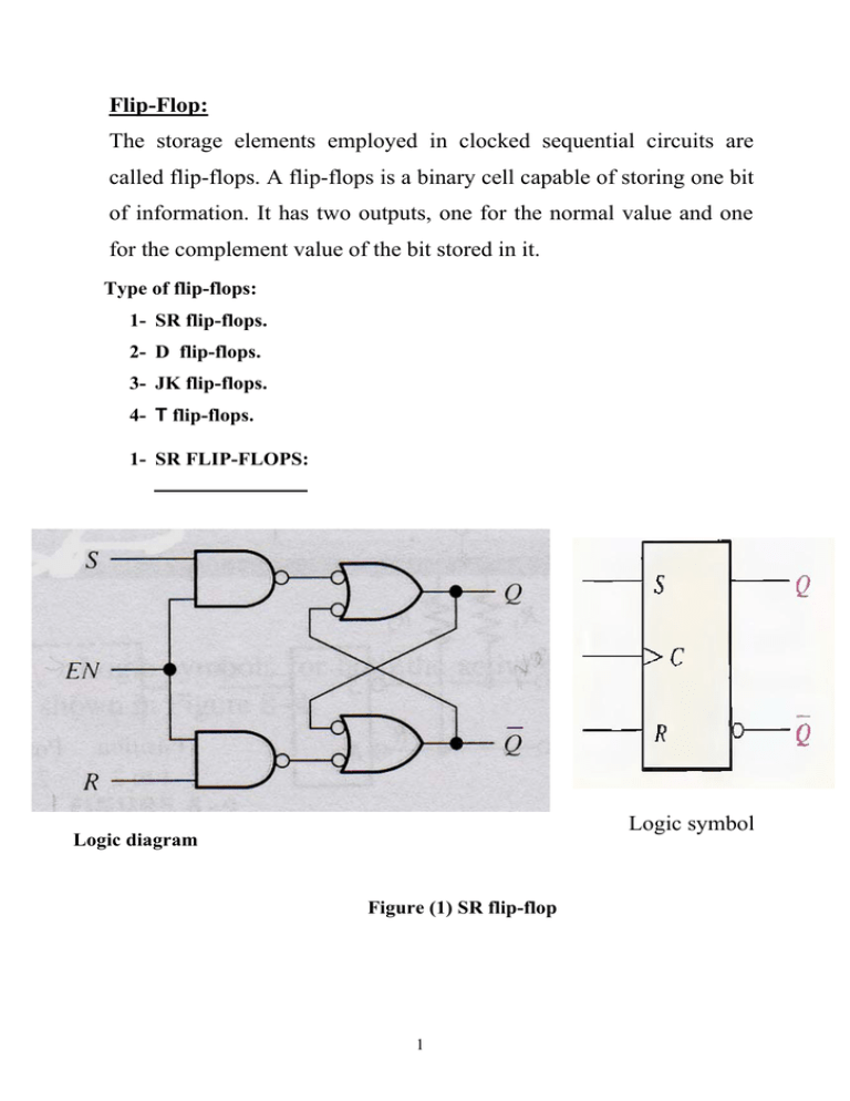
Flip-Flop: The storage elements employed in clocked sequential circuits are called flip-flops. A flip-flops is a binary cell capable of storing one bit of information. It has two outputs, one for the normal value and one for the complement value of the bit stored in it. Type of flip-flops: 1- SR flip-flops. 2- D flip-flops. 3- JK flip-flops. 4- T flip-flops. 1- SR FLIP-FLOPS: Logic symbol Logic diagram Figure (1) SR flip-flop 1 Inputs Outputs − Comments S R CLK Q Q 0 0 ↑ Q0 Q0 No change 0 1 ↑ 0 1 Reset 1 0 ↑ 1 0 Set 1 1 ↑ − ? Invalid − ? Truth table for SR flip-flop 2- D FLIP-FLOPS: FIGURE (2) D Flip-flop Inputs Outputs − D CLK Q Q Comments 1 ↑ 1 0 Set(stor1) 0 ↑ 0 1 Reset(stor0) Truth table for D flip-flop 2 3- J K FLIP-FLOPS: Logic symbol Logic diagram Figure (3) JK Flip-flop Inputs Outputs − Comments J K CLK Q Q 0 0 ↑ Q0 Q0 No change 0 1 ↑ 0 1 Reset 1 0 ↑ 1 0 Set 1 1 ↑ Q0 Q0 Toggle − − Truth table for JK flip-flop 3 4- T FLIP-FLOPS: Logic symbol Logic diagram FIGURE (4) D Flip-flop Truth table for T flip-flop State Diagram A state diagram is a graph that shows the flip-flop’s operations in terms of how it transitions from one state to another. The nodes are labeled with the states and the directed arcs are labeled with the input signals that cause the transition to go from one state to the next. Figure 5 shows the state diagram for the SR flip-flop. For example, to go from state Q = 0 to the state Q = 1, the two inputs S and R have to be 1 and 0 respectively. Similarly, if the current state is Q = 0 and we want to remain in that state, then SR need to be 00 or 01. Figure 5. State diagram for the SR flip-flop. 4 5 6


![Sequential Circuits-Radha Iyer[cs 151]](http://s3.studylib.net/store/data/009253826_1-9ea30ee9b3f2c51b0308a42ccf258b21-300x300.png)
