7.6: Modeling Pulse Width Modulator Lecture 24: Modulator Modeling, Bode Plot Review 10/13/2015
advertisement
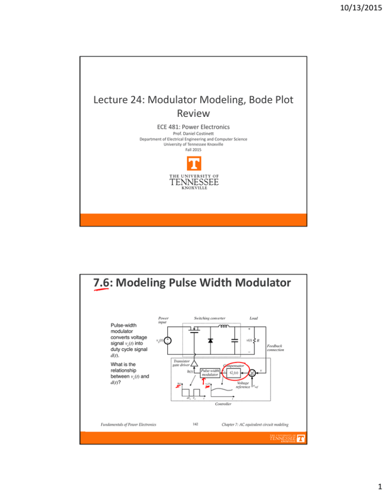
10/13/2015 Lecture 24: Modulator Modeling, Bode Plot Review ECE 481: Power Electronics Prof. Daniel Costinett Department of Electrical Engineering and Computer Science University of Tennessee Knoxville Fall 2015 7.6: Modeling Pulse Width Modulator 1 10/13/2015 Functional PWM Model Equations of PWM Model 2 10/13/2015 Perturbed Behavior of PWM Sampling Behavior of PWM 3 10/13/2015 Chapter 7: Summary 1. The CCM converter analytical techniques of Chapters 2 and 3 can be extended to predict converter ac behavior. The key step is to average the converter waveforms over one switching period. This removes the switching harmonics, thereby exposing directly the desired dc and low‐frequency ac components of the waveforms. In particular, expressions for the averaged inductor voltages, capacitor currents, and converter input current are usually found. 2. Since switching converters are nonlinear systems, it is desirable to construct small‐signal linearized models. This is accomplished by perturbing and linearizing the averaged model about a quiescent operating point. 3. Ac equivalent circuits can be constructed, in the same manner used in Chapter 3 to construct dc equivalent circuits. If desired, the ac equivalent circuits may be refined to account for the effects of converter losses and other nonidealities. 4. The conventional pulse‐width modulator circuit has linear gain, dependent on the slope of the sawtooth waveform, or equivalently on its peak‐to‐peak magnitude. Chapter 8: Converter Transfer Functions 4 10/13/2015 Converter Transfer Functions Buck Boost Model 5 10/13/2015 Control‐to‐output Transfer Function Design‐Oriented Analysis 6 10/13/2015 Chapter 8: Design‐Oriented Analysis 8.1 Review of Bode Plots 7 10/13/2015 Logarithm Review Plotting on Logarithmic Axes 8


