Extended Abstract for 12 Int. Symposium on Applications of Laser
advertisement
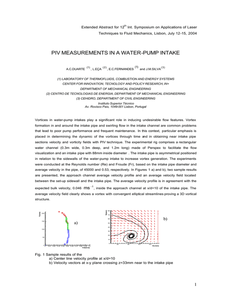
th Extended Abstract for 12 Int. Symposium on Applications of Laser Techniques to Fluid Mechanics, Lisbon, July 12-15, 2004 PIV MEASUREMENTS IN A WATER-PUMP INTAKE A.C.DUARTE (1) , L.EÇA (2) , E.C.FERNANDES (1) and J.M.SILVA (3) (1) LABORATORY OF THERMOFLUIDS, COMBUSTION AND ENERGY SYSTEMS CENTER FOR INNOVATION, TECNOLOGY AND POLICY RESEARCH, IN+ DEPARTMENT OF MECHANICAL ENGINEERING (2) CENTRO DE TECNOLOGIAS DE ENERGIA, DEPARTMENT OF MECHANICAL ENGINEERING (3) CEHIDRO, DEPARTMENT OF CIVIL ENGINEERING Instituto Superior Técnico Av. Rovisco Pais, 1049-001 Lisbon, Portugal Vortices in water-pump intakes play a significant role in inducing undesirable flow features. Vortex formation in and around the intake pipe and swirling flow in the intake channel are common problems that lead to poor pump performance and frequent maintenance. In this context, particular emphasis is placed in determining the dynamic of the vortices through time and in obtaining near intake pipe sections velocity and vorticity fields with PIV technique. The experimental rig comprises a rectangular water channel (0.3m wide, 0.3m deep, and 1.2m long) made of Perspex to facilitate the flow visualization and an intake pipe with 88mm inside diameter . The intake pipe is asymmetrical positioned in relation to the sidewalls of the water-pump intake to increase vortex generation. The experiments were conducted at the Reynolds number (Re) and Froude (Fr), based on the intake pipe diameter and average velocity in the pipe, of 45000 and 0.53, respectively. In Figures 1 a) and b), two sample results are presented, the approach channel average velocity profile and an average velocity field located between the set-up sidewall and the intake pipe. The average velocity profile is in agreement with the ms −1 , expected bulk velocity, 0.046 inside the approach channel at x/d=10 of the intake pipe. The average velocity field clearly shows a vortex with convergent elliptical streamlines proving a 3D vortical Y(mm) Y(mm) structure. 200 80 70 b) 60 150 a) 50 40 100 30 20 50 10 0 0 0 0.01 0.02 0.03 0 .04 0.05 0.06 0.07 0.08 0.09 0.1 20 40 60 80 X( mm) V el(m/s) Fig. 1 Sample results of the a) Center line velocity profile at x/d=10 b) Velocity vectors at x-y plane crossing z=33mm near to the intake pipe 1
