2023-11-19T08:15:40+03:00[Europe/Moscow] en true <p><strong>Link Aggregation Group</strong></p><p>- Dynamic LAG IEEE <span class="tt-bg-red">_____</span></p><p>- Multiple physical links to act as a single logical link</p><p>- New bandwidth is aggregate of all the links in the group</p><p>- Traffic is shared across the links in the group</p><p>- In the event of link failure, the data traffic is moved to another link in the group providing seamless failover</p>, <p><strong>Link Aggregation Group</strong></p><p>- Dynamic LAG IEEE 803.2ad</p><p>- Multiple physical links to act as a single <span class="tt-bg-red">____</span> link</p><p>- New bandwidth is aggregate of all the links in the group</p><p>- Traffic is shared across the links in the group</p><p>- In the event of link failure, the data traffic is moved to another link in the group providing seamless failover</p>, <p><strong>Link Aggregation Group</strong></p><p>- Dynamic LAG IEEE 803.2ad</p><p>- Multiple physical links to act as a single logical link</p><p>- New bandwidth is <span class="tt-bg-red">_____</span> of all the links in the group</p><p>- Traffic is shared across the links in the group</p><p>- In the event of link failure, the data traffic is moved to another link in the group providing seamless failover</p>, <p><strong>Multi-Chassis LAG (MLAG)</strong></p><p>- Enhancement to standard LAG</p><p>- Splits the LAG group across different nodes</p><p>- Providing link, <span class="tt-bg-red">____</span> and <span class="tt-bg-red">___</span> redundancy</p><p>- No layer 2 loop thus an Active-Active topology</p><p>- Sub-second failover based on the physical link failure</p>, <p><strong>Multi-Chassis LAG (MLAG)</strong></p><p>- Enhancement to standard LAG</p><p>- Splits the LAG group across different nodes</p><p>- Providing link, module and node redundancy</p><p>- No layer 2 loop thus an Active-<span class="tt-bg-red">____</span> topology</p><p>- Sub-second failover based on the physical link failure</p>, <p><strong>Multi-Chassis LAG (MLAG)</strong></p><p>- Enhancement to standard LAG</p><p>- Splits the LAG group across different nodes</p><p>- Providing link, module and node redundancy</p><p>- No layer 2 loop thus an Active-Active topology</p><p>- Sub-<span class="tt-bg-red">___</span> failover based on the physical link failure</p>, <p>MLAG is Standard <span class="tt-bg-red">____</span> based</p>, <p><strong>MLAG is standard 802.3ad based:</strong></p><p>- Dynamic LACP or <span class="tt-bg-red">____</span> configuration&nbsp;</p><p>- Transparent to attached client device</p><p>- Support for third-party vendors and servers</p>, <p><strong>MLAG is standard 802.3ad based:</strong></p><p>- Dynamic LACP or static configuration&nbsp;</p><p>- <span class="tt-bg-red">_____</span> to attached client device</p><p>- Support for third-party vendors and servers</p>, <p>Without MLAG, redundant connections from end host devices would either be configured in an <span class="tt-bg-red">____</span> scenario or blocked via spanning-tree reducing the total bandwidth used.</p>, <p>Without MLAG, redundant connections from end host devices would either be configured in an active/passive scenario or blocked via <span class="tt-bg-red">____</span> reducing the total bandwidth used.</p>, <p>Using MLAG, all redundant links to downstream devices/hosts can be <span class="tt-bg-red">___</span> into a single LAG to utilize the entire bandwidth available.</p>, <p>A pair of physical switches</p>, <p>A single switch within an MLAG domain</p>, <p>Non-proprietary Ethernet physical link between MLAG peers required to synchronize state between MLAG peers and carry user data</p>, <p>One or more user-facing physical ports that forms an MLAG</p>, <p>This is a combined user-facing port-channel between MLAG peers consisting of MLAG member ports on both MLAG peers</p>, <p>A VLAN used exclusively on the MLAG peer-link, in order to aid control-plane communication between MLAG peers.</p>, <p>To permit the MLAG communication between peers,</p><p>appropriate MLAG-related UDP and TCP entries should be present in the default control plane ACL or in a custom ACL if one is used instead:</p><p>- permit ip any any tracked</p><p>- permit tcp <span class="tt-bg-red">___</span></p><p>- permit udp <span class="tt-bg-red">___</span></p>, <p><strong>MLAG Configuration</strong></p><p><strong>Step 1: Configure the Peer link</strong></p><p>Configure the peer link as a standard <span class="tt-bg-red">_____</span></p><p>- Any Ethernet port on the switch of enough capacity</p><p>- Recommended minimum of two ports for redundancy</p><p>- Under steady state conditions data traffic doesn't flow across the peer link</p><p>- Bandwidth not required to be large under the steady conditions</p>, <p><strong>MLAG Configuration</strong></p><p><strong>Step 1: Configure the Peer link</strong></p><p>Configure the peer link as a standard port-channel</p><p>- Any Ethernet port on the switch of enough capacity</p><p>- Recommended minimum of two ports for <span class="tt-bg-red">_____</span></p><p>- Under steady state conditions data traffic doesn't flow across the peer link</p><p>- Bandwidth not required to be large under the steady conditions</p>, <p><strong>MLAG Configuration</strong></p><p><strong>Step 1: Configure the Peer link</strong></p><p>Configure the peer link as a standard port-channel</p><p>- Any Ethernet port on the switch of enough capacity</p><p>- Recommended minimum of two ports for redundancy</p><p>- Under steady state conditions <span class="tt-bg-red">_____</span> doesn't flow across the peer link</p><p>- Bandwidth not required to be large under the steady conditions</p>, <p>Create the port-channel as a ____ port.</p>, <p><strong>MLAG Configuration</strong></p><p><strong>Step 2: Create the Peer link VLAN</strong></p><p>- VLAN used for MLAG <span class="tt-bg-red">_____</span> session</p><p>- SVI needs to be created for the VLAN</p><p>- Spanning tree must be disabled on the VLAN</p><p>- Peer link VLAN recommended to be configured within a "trunk group"</p><p>- Trunk group needs to be explicitly configured on the peer link</p>, <p><strong>MLAG Configuration</strong></p><p><strong>Step 2: Create the <span class="tt-bg-red">____</span></strong></p><p>- VLAN used for MLAG TCP/UDP session</p><p>- SVI needs to be created for the VLAN</p><p>- Spanning tree must be disabled on the VLAN</p><p>- Peer link VLAN recommended to be configured within a "trunk group"</p><p>- Trunk group needs to be explicitly configured on the peer link</p>, <p><strong>MLAG Configuration</strong></p><p><strong>Step 2: Create the Peer link VLAN</strong></p><p>- VLAN used for MLAG TCP/UDP session</p><p>- SVI needs to be created for the VLAN</p><p>- Spanning tree must be <span class="tt-bg-red">____</span> on the VLAN</p><p>- Peer link VLAN recommended to be configured within a "trunk group"</p><p>- Trunk group needs to be explicitly configured on the peer link</p>, <p><strong>MLAG Configuration</strong></p><p><strong>Step 2: Create the Peer link VLAN</strong></p><p>- VLAN used for MLAG TCP/UDP session</p><p>- SVI needs to be created for the VLAN</p><p>- Spanning tree must be disabled on the VLAN</p><p>- Peer link VLAN recommended to be configured within a <span class="tt-bg-red">____</span></p><p>- <span class="tt-bg-red">____</span> needs to be explicitly configured on the peer link</p>, <p><strong>MLAG Configuration</strong></p><p><strong>Step 3: Configure the MLAG domain</strong></p><p>- All MLAG configuration achieved under the “mlag” context</p><p>- Define the MLAG domain-ID, must be identical on both switches (<span class="tt-bg-red">____</span>)</p><p>- Define the port-channel to be used for the peer link</p><p>- Define the local interface to be used for the MLAG session</p><p>- Define the remote peer’s IP address for creating the MLAG session</p>, <p><strong>MLAG Configuration</strong></p><p><strong>Step 3: Configure the MLAG domain</strong></p><p>- All MLAG configuration achieved under the “mlag” context</p><p>- Define the MLAG domain-ID, must be identical on both switches (case</p><p>sensitive)</p><p>- Define the port-channel to be used for the <span class="tt-bg-red">____</span></p><p>- Define the local interface to be used for the MLAG session</p><p>- Define the remote peer’s IP address for creating the MLAG session</p>, <p><strong>MLAG Configuration</strong></p><p><strong>Step 3: Configure the MLAG domain</strong></p><p>- All MLAG configuration achieved under the “mlag” context</p><p>- Define the MLAG domain-ID, must be identical on both switches (case sensitive)</p><p>- Define the port-channel to be used for the peer link</p><p>- Define the <span class="tt-bg-red">____</span> to be used for the MLAG session</p><p>- Define the remote peer’s IP address for creating the MLAG session</p>, <p><strong>MLAG Configuration</strong></p><p><strong>Step 3: Configure the MLAG domain</strong></p><p>- All MLAG configuration achieved under the “mlag” context</p><p>- Define the MLAG domain-ID, must be identical on both switches (case</p><p>sensitive)</p><p>- Define the port-channel to be used for the peer link</p><p>- Define the local interface to be used for the MLAG session</p><p>- Define the remote peer’s <span class="tt-bg-red">____</span> for creating the MLAG session</p>, <p><strong>MLAG Configuration</strong></p><p><strong>Step 3: Configure the <span class="tt-bg-red">____</span></strong></p><p>- All MLAG configuration achieved under the “mlag” context</p><p>- Define the MLAG domain-ID, must be identical on both switches (case</p><p>sensitive)</p><p>- Define the port-channel to be used for the peer link</p><p>- Define the local interface to be used for the MLAG session</p><p>- Define the remote peer’s IP address for creating the MLAG session</p>, <p><strong>MLAG Configuration</strong></p><p><strong>Step 4: Create the MLAG port members</strong></p><p>- MLAG port members created as standard port-channels</p><p>- Port-channel created on each MLAG peer</p><p>- Static, passive or active <span class="tt-bg-red">____</span> configurable on each port-channel</p><p>- The port-channel can contain one or multiple ports on each peer switch</p><p>- The “MLAG &lt;#&gt;” statement binds the port-channel on the peers together</p>, <p><strong>MLAG Configuration</strong></p><p><strong>Step 4: Create the MLAG port members</strong></p><p>- MLAG port members created as standard port-channels</p><p>- Port-channel created on each MLAG peer</p><p>- Static, passive or active LACP configurable on each port-channel</p><p>- The port-channel can contain one or multiple ports on each peer switch</p><p>- "<span class="tt-bg-red">____</span>" command binds the port-channel on the peers together</p>, <p>Link Aggregation Groups provide ____ and ____ redundancy</p> flashcards
MLAG Basics

MLAG Basics

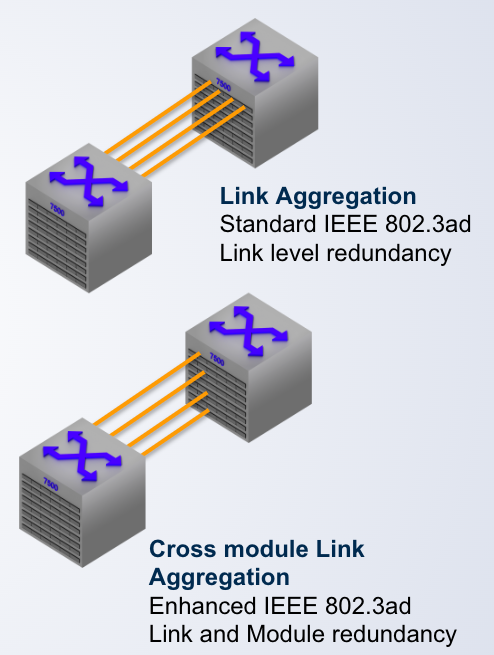
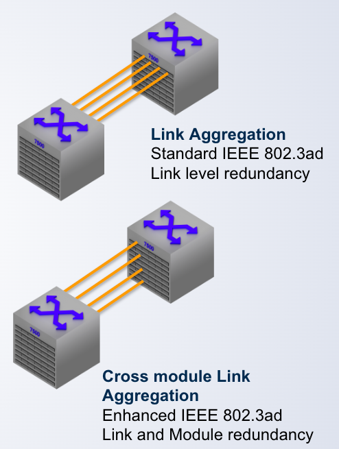
  • Link Aggregation Group- Dynamic LAG IEEE _____- Multiple physical links to act as a single logical link- New bandwidth is aggregate of all the links in the group- Traffic is shared across the links in the group- In the event of link failure, the data traffic is moved to another link in the group providing seamless failover

    Link Aggregation Group

    - Dynamic LAG IEEE _____

    - Multiple physical links to act as a single logical link

    - New bandwidth is aggregate of all the links in the group

    - Traffic is shared across the links in the group

    - In the event of link failure, the data traffic is moved to another link in the group providing seamless failover

    803.2ad

  • Link Aggregation Group- Dynamic LAG IEEE 803.2ad- Multiple physical links to act as a single ____ link- New bandwidth is aggregate of all the links in the group- Traffic is shared across the links in the group- In the event of link failure, the data traffic is moved to another link in the group providing seamless failover

    Link Aggregation Group

    - Dynamic LAG IEEE 803.2ad

    - Multiple physical links to act as a single ____ link

    - New bandwidth is aggregate of all the links in the group

    - Traffic is shared across the links in the group

    - In the event of link failure, the data traffic is moved to another link in the group providing seamless failover

    logical

  • Link Aggregation Group- Dynamic LAG IEEE 803.2ad- Multiple physical links to act as a single logical link- New bandwidth is _____ of all the links in the group- Traffic is shared across the links in the group- In the event of link failure, the data traffic is moved to another link in the group providing seamless failover

    Link Aggregation Group

    - Dynamic LAG IEEE 803.2ad

    - Multiple physical links to act as a single logical link

    - New bandwidth is _____ of all the links in the group

    - Traffic is shared across the links in the group

    - In the event of link failure, the data traffic is moved to another link in the group providing seamless failover

    aggregate

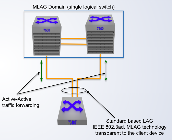
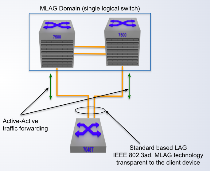
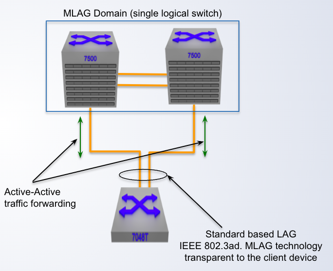
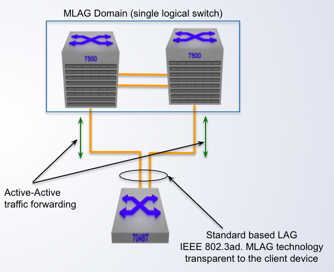
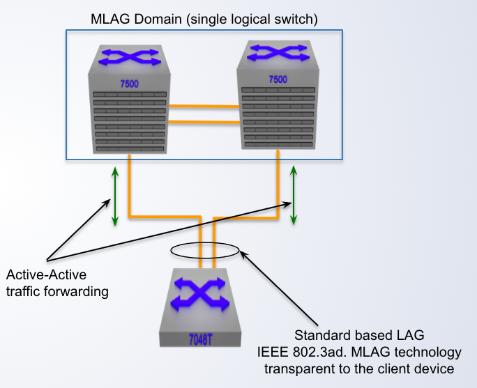
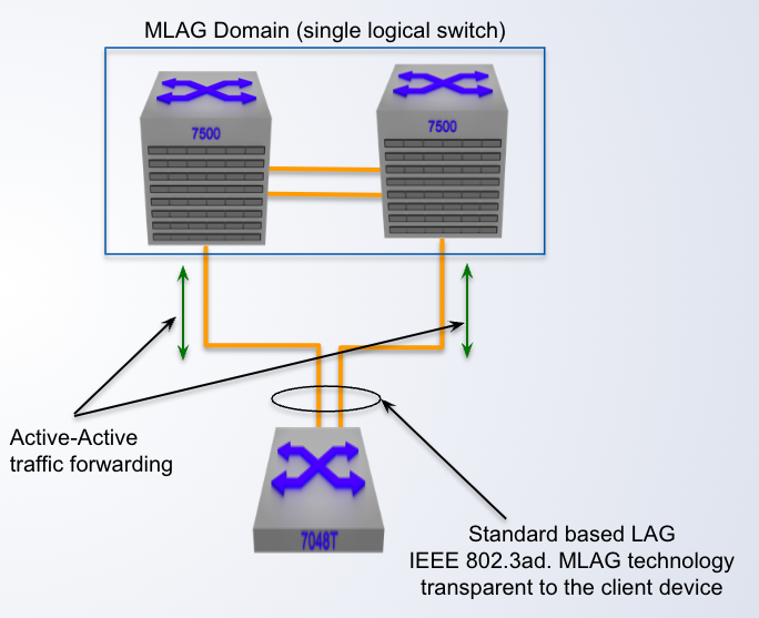
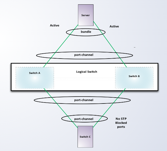
  • Multi-Chassis LAG (MLAG)- Enhancement to standard LAG- Splits the LAG group across different nodes- Providing link, ____ and ___ redundancy- No layer 2 loop thus an Active-Active topology- Sub-second failover based on the physical link failure

    Multi-Chassis LAG (MLAG)

    - Enhancement to standard LAG

    - Splits the LAG group across different nodes

    - Providing link, ____ and ___ redundancy

    - No layer 2 loop thus an Active-Active topology

    - Sub-second failover based on the physical link failure

    module, node

  • Multi-Chassis LAG (MLAG)- Enhancement to standard LAG- Splits the LAG group across different nodes- Providing link, module and node redundancy- No layer 2 loop thus an Active-____ topology- Sub-second failover based on the physical link failure

    Multi-Chassis LAG (MLAG)

    - Enhancement to standard LAG

    - Splits the LAG group across different nodes

    - Providing link, module and node redundancy

    - No layer 2 loop thus an Active-____ topology

    - Sub-second failover based on the physical link failure

    active

  • Multi-Chassis LAG (MLAG)- Enhancement to standard LAG- Splits the LAG group across different nodes- Providing link, module and node redundancy- No layer 2 loop thus an Active-Active topology- Sub-___ failover based on the physical link failure

    Multi-Chassis LAG (MLAG)

    - Enhancement to standard LAG

    - Splits the LAG group across different nodes

    - Providing link, module and node redundancy

    - No layer 2 loop thus an Active-Active topology

    - Sub-___ failover based on the physical link failure

    second

  • MLAG is Standard ____ based

    MLAG is Standard ____ based

    802.3ad

  • MLAG is standard 802.3ad based:- Dynamic LACP or ____ configuration&nbsp;- Transparent to attached client device- Support for third-party vendors and servers

    MLAG is standard 802.3ad based:

    - Dynamic LACP or ____ configuration 

    - Transparent to attached client device

    - Support for third-party vendors and servers

    static

  • MLAG is standard 802.3ad based:- Dynamic LACP or static configuration&nbsp;- _____ to attached client device- Support for third-party vendors and servers

    MLAG is standard 802.3ad based:

    - Dynamic LACP or static configuration 

    - _____ to attached client device

    - Support for third-party vendors and servers

    transparent

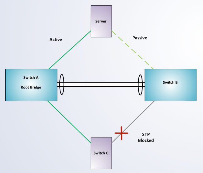
  • Without MLAG, redundant connections from end host devices would either be configured in an ____ scenario or blocked via spanning-tree reducing the total bandwidth used.

    Without MLAG, redundant connections from end host devices would either be configured in an ____ scenario or blocked via spanning-tree reducing the total bandwidth used.

    active/passive

  • Without MLAG, redundant connections from end host devices would either be configured in an active/passive scenario or blocked via ____ reducing the total bandwidth used.

    Without MLAG, redundant connections from end host devices would either be configured in an active/passive scenario or blocked via ____ reducing the total bandwidth used.

    spanning-tree

  • Using MLAG, all redundant links to downstream devices/hosts can be ___ into a single LAG to utilize the entire bandwidth available.

    Using MLAG, all redundant links to downstream devices/hosts can be ___ into a single LAG to utilize the entire bandwidth available.

    bundled

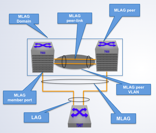
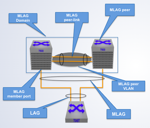
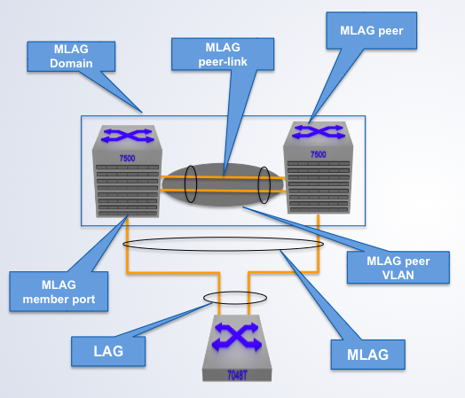
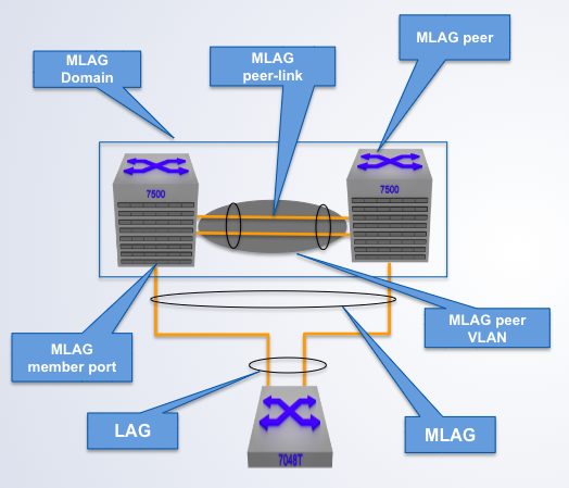
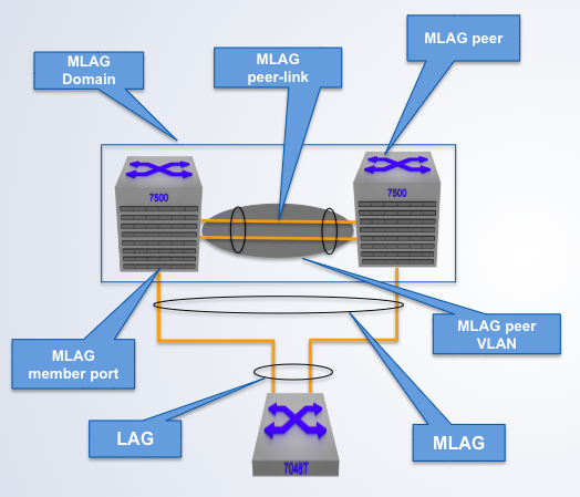
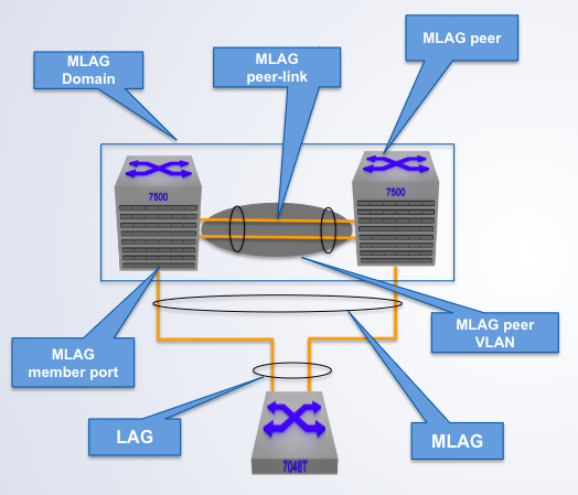
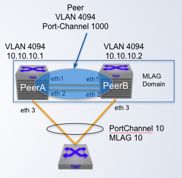
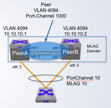
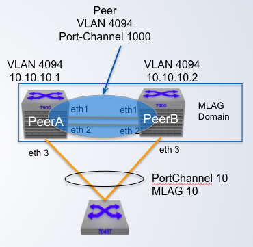
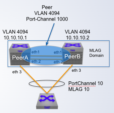
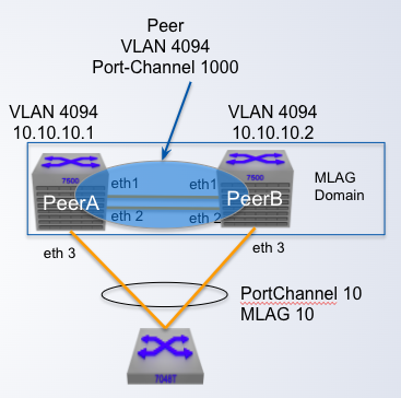
  • A pair of physical switches

    A pair of physical switches

    MLAG Domain

  • A single switch within an MLAG domain

    A single switch within an MLAG domain

    MLAG Peer

  • Non-proprietary Ethernet physical link between MLAG peers required to synchronize state between MLAG peers and carry user data

    Non-proprietary Ethernet physical link between MLAG peers required to synchronize state between MLAG peers and carry user data

    MLAG peer-link

  • One or more user-facing physical ports that forms an MLAG

    One or more user-facing physical ports that forms an MLAG

    MLAG member port

  • This is a combined user-facing port-channel between MLAG peers consisting of MLAG member ports on both MLAG peers

    This is a combined user-facing port-channel between MLAG peers consisting of MLAG member ports on both MLAG peers

    MLAG port-channel

  • A VLAN used exclusively on the MLAG peer-link, in order to aid control-plane communication between MLAG peers.

    A VLAN used exclusively on the MLAG peer-link, in order to aid control-plane communication between MLAG peers.

    MLAG VLAN

  • To permit the MLAG communication between peers,appropriate MLAG-related UDP and TCP entries should be present in the default control plane ACL or in a custom ACL if one is used instead:- permit ip any any tracked- permit tcp ___- permit udp ___

    To permit the MLAG communication between peers,

    appropriate MLAG-related UDP and TCP entries should be present in the default control plane ACL or in a custom ACL if one is used instead:

    - permit ip any any tracked

    - permit tcp ___

    - permit udp ___

    any any eq mlag ttl eq 255

  • MLAG ConfigurationStep 1: Configure the Peer linkConfigure the peer link as a standard _____- Any Ethernet port on the switch of enough capacity- Recommended minimum of two ports for redundancy- Under steady state conditions data traffic doesn't flow across the peer link- Bandwidth not required to be large under the steady conditions

    MLAG Configuration

    Step 1: Configure the Peer link

    Configure the peer link as a standard _____

    - Any Ethernet port on the switch of enough capacity

    - Recommended minimum of two ports for redundancy

    - Under steady state conditions data traffic doesn't flow across the peer link

    - Bandwidth not required to be large under the steady conditions

    port-channel

  • MLAG ConfigurationStep 1: Configure the Peer linkConfigure the peer link as a standard port-channel- Any Ethernet port on the switch of enough capacity- Recommended minimum of two ports for _____- Under steady state conditions data traffic doesn't flow across the peer link- Bandwidth not required to be large under the steady conditions

    MLAG Configuration

    Step 1: Configure the Peer link

    Configure the peer link as a standard port-channel

    - Any Ethernet port on the switch of enough capacity

    - Recommended minimum of two ports for _____

    - Under steady state conditions data traffic doesn't flow across the peer link

    - Bandwidth not required to be large under the steady conditions

    redundancy

  • MLAG ConfigurationStep 1: Configure the Peer linkConfigure the peer link as a standard port-channel- Any Ethernet port on the switch of enough capacity- Recommended minimum of two ports for redundancy- Under steady state conditions _____ doesn't flow across the peer link- Bandwidth not required to be large under the steady conditions

    MLAG Configuration

    Step 1: Configure the Peer link

    Configure the peer link as a standard port-channel

    - Any Ethernet port on the switch of enough capacity

    - Recommended minimum of two ports for redundancy

    - Under steady state conditions _____ doesn't flow across the peer link

    - Bandwidth not required to be large under the steady conditions

    data traffic

  • Create the port-channel as a ____ port.

    Create the port-channel as a ____ port.

    trunk

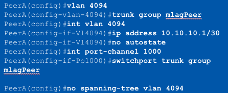
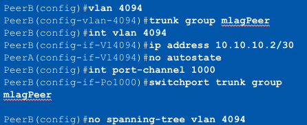
  • MLAG ConfigurationStep 2: Create the Peer link VLAN- VLAN used for MLAG _____ session- SVI needs to be created for the VLAN- Spanning tree must be disabled on the VLAN- Peer link VLAN recommended to be configured within a "trunk group"- Trunk group needs to be explicitly configured on the peer link

    MLAG Configuration

    Step 2: Create the Peer link VLAN

    - VLAN used for MLAG _____ session

    - SVI needs to be created for the VLAN

    - Spanning tree must be disabled on the VLAN

    - Peer link VLAN recommended to be configured within a "trunk group"

    - Trunk group needs to be explicitly configured on the peer link

    TCP/UDP

  • MLAG ConfigurationStep 2: Create the ____- VLAN used for MLAG TCP/UDP session- SVI needs to be created for the VLAN- Spanning tree must be disabled on the VLAN- Peer link VLAN recommended to be configured within a "trunk group"- Trunk group needs to be explicitly configured on the peer link

    MLAG Configuration

    Step 2: Create the ____

    - VLAN used for MLAG TCP/UDP session

    - SVI needs to be created for the VLAN

    - Spanning tree must be disabled on the VLAN

    - Peer link VLAN recommended to be configured within a "trunk group"

    - Trunk group needs to be explicitly configured on the peer link

    peer link VLAN

  • MLAG ConfigurationStep 2: Create the Peer link VLAN- VLAN used for MLAG TCP/UDP session- SVI needs to be created for the VLAN- Spanning tree must be ____ on the VLAN- Peer link VLAN recommended to be configured within a "trunk group"- Trunk group needs to be explicitly configured on the peer link

    MLAG Configuration

    Step 2: Create the Peer link VLAN

    - VLAN used for MLAG TCP/UDP session

    - SVI needs to be created for the VLAN

    - Spanning tree must be ____ on the VLAN

    - Peer link VLAN recommended to be configured within a "trunk group"

    - Trunk group needs to be explicitly configured on the peer link

    disabled

  • MLAG ConfigurationStep 2: Create the Peer link VLAN- VLAN used for MLAG TCP/UDP session- SVI needs to be created for the VLAN- Spanning tree must be disabled on the VLAN- Peer link VLAN recommended to be configured within a ____- ____ needs to be explicitly configured on the peer link

    MLAG Configuration

    Step 2: Create the Peer link VLAN

    - VLAN used for MLAG TCP/UDP session

    - SVI needs to be created for the VLAN

    - Spanning tree must be disabled on the VLAN

    - Peer link VLAN recommended to be configured within a ____

    - ____ needs to be explicitly configured on the peer link

    trunk group

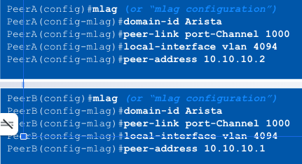
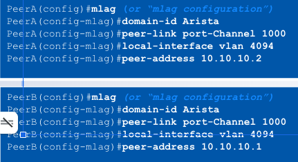
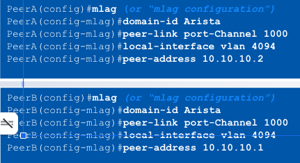
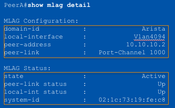
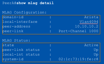
  • MLAG ConfigurationStep 3: Configure the MLAG domain- All MLAG configuration achieved under the “mlag” context- Define the MLAG domain-ID, must be identical on both switches (____)- Define the port-channel to be used for the peer link- Define the local interface to be used for the MLAG session- Define the remote peer’s IP address for creating the MLAG session

    MLAG Configuration

    Step 3: Configure the MLAG domain

    - All MLAG configuration achieved under the “mlag” context

    - Define the MLAG domain-ID, must be identical on both switches (____)

    - Define the port-channel to be used for the peer link

    - Define the local interface to be used for the MLAG session

    - Define the remote peer’s IP address for creating the MLAG session

    case sensitive

  • MLAG ConfigurationStep 3: Configure the MLAG domain- All MLAG configuration achieved under the “mlag” context- Define the MLAG domain-ID, must be identical on both switches (casesensitive)- Define the port-channel to be used for the ____- Define the local interface to be used for the MLAG session- Define the remote peer’s IP address for creating the MLAG session

    MLAG Configuration

    Step 3: Configure the MLAG domain

    - All MLAG configuration achieved under the “mlag” context

    - Define the MLAG domain-ID, must be identical on both switches (case

    sensitive)

    - Define the port-channel to be used for the ____

    - Define the local interface to be used for the MLAG session

    - Define the remote peer’s IP address for creating the MLAG session

    peer link

  • MLAG ConfigurationStep 3: Configure the MLAG domain- All MLAG configuration achieved under the “mlag” context- Define the MLAG domain-ID, must be identical on both switches (case sensitive)- Define the port-channel to be used for the peer link- Define the ____ to be used for the MLAG session- Define the remote peer’s IP address for creating the MLAG session

    MLAG Configuration

    Step 3: Configure the MLAG domain

    - All MLAG configuration achieved under the “mlag” context

    - Define the MLAG domain-ID, must be identical on both switches (case sensitive)

    - Define the port-channel to be used for the peer link

    - Define the ____ to be used for the MLAG session

    - Define the remote peer’s IP address for creating the MLAG session

    local interface

  • MLAG ConfigurationStep 3: Configure the MLAG domain- All MLAG configuration achieved under the “mlag” context- Define the MLAG domain-ID, must be identical on both switches (casesensitive)- Define the port-channel to be used for the peer link- Define the local interface to be used for the MLAG session- Define the remote peer’s ____ for creating the MLAG session

    MLAG Configuration

    Step 3: Configure the MLAG domain

    - All MLAG configuration achieved under the “mlag” context

    - Define the MLAG domain-ID, must be identical on both switches (case

    sensitive)

    - Define the port-channel to be used for the peer link

    - Define the local interface to be used for the MLAG session

    - Define the remote peer’s ____ for creating the MLAG session

    IP address

  • MLAG ConfigurationStep 3: Configure the ____- All MLAG configuration achieved under the “mlag” context- Define the MLAG domain-ID, must be identical on both switches (casesensitive)- Define the port-channel to be used for the peer link- Define the local interface to be used for the MLAG session- Define the remote peer’s IP address for creating the MLAG session

    MLAG Configuration

    Step 3: Configure the ____

    - All MLAG configuration achieved under the “mlag” context

    - Define the MLAG domain-ID, must be identical on both switches (case

    sensitive)

    - Define the port-channel to be used for the peer link

    - Define the local interface to be used for the MLAG session

    - Define the remote peer’s IP address for creating the MLAG session

    MLAG domain

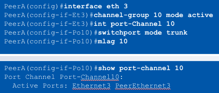
  • MLAG ConfigurationStep 4: Create the MLAG port members- MLAG port members created as standard port-channels- Port-channel created on each MLAG peer- Static, passive or active ____ configurable on each port-channel- The port-channel can contain one or multiple ports on each peer switch- The “MLAG &lt;#&gt;” statement binds the port-channel on the peers together

    MLAG Configuration

    Step 4: Create the MLAG port members

    - MLAG port members created as standard port-channels

    - Port-channel created on each MLAG peer

    - Static, passive or active ____ configurable on each port-channel

    - The port-channel can contain one or multiple ports on each peer switch

    - The “MLAG <#>” statement binds the port-channel on the peers together

    LACP

  • MLAG ConfigurationStep 4: Create the MLAG port members- MLAG port members created as standard port-channels- Port-channel created on each MLAG peer- Static, passive or active LACP configurable on each port-channel- The port-channel can contain one or multiple ports on each peer switch- "____" command binds the port-channel on the peers together

    MLAG Configuration

    Step 4: Create the MLAG port members

    - MLAG port members created as standard port-channels

    - Port-channel created on each MLAG peer

    - Static, passive or active LACP configurable on each port-channel

    - The port-channel can contain one or multiple ports on each peer switch

    - "____" command binds the port-channel on the peers together

    MLAG <#>

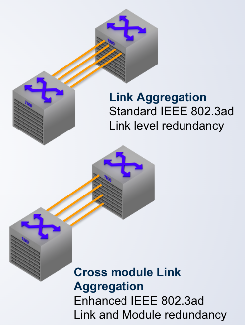
  • Link Aggregation Groups provide ____ and ____ redundancy

    link, module