-
What is the layout of the modern cockpit and what are its components?
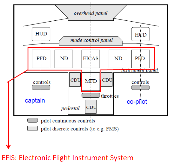
HUD : Head Up Display
PFD : Primary Flight Display
ND : Navigation Display
MFD : Multi-Function Display
EICAS : Engine indication & Crew Alerting System(Boeing)
ECAM : Electronic Centralised Aircraft Monitor (Airbus)
CDU : Command Display Unit
-
What is the Flight Director (FD)? What does it display and how does it function?
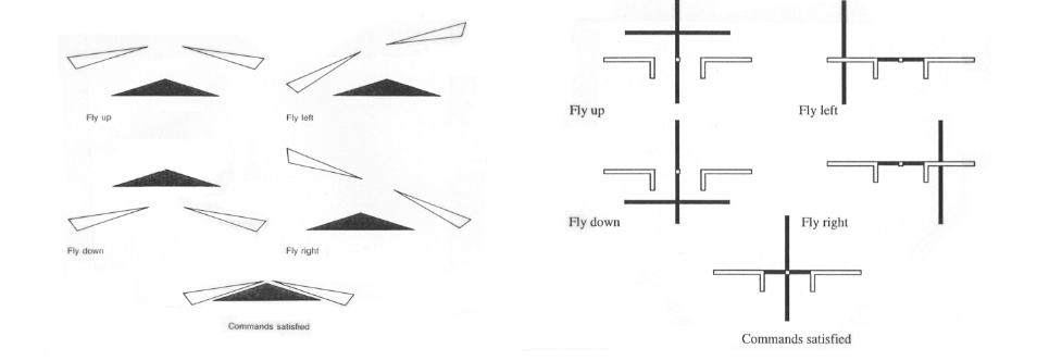
A flight director (FD) is a flight instrument that is overlaid on the attitude indicator that shows the pilot of an aircraft the attitude required to execute the desired flight path. Flight directors are mostly commonly used during approach and landing. They can be used with or without autopilot systems.
The FD usually receives input from an Air Data Computer (ADC) and a flight data computer. It integrates all of the data such as speed, position, closure, drift, track, desired course, and altitude into a command signal. The command signal is displayed on the attitude indicator in the form of command bars or V-bars, which show the pitch and roll inputs necessary to achieve the selected targets. "Follow the needle"
-
How does a FD work together with an Autopilot?
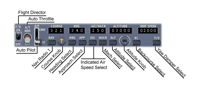
The Autopilot can do the same as the Flight Director, but here the automated flight control system directly controls the aircraft. If the autopilot is engaged, autopilot flies the plane to follow the flight director. The flight director serves as a visual indication of where the autopilot wants the plane to go.
The procedure to engage them is to first turn on the flight director, which will show where the autopilot wants the plane to be, and then to engage the autopilot, which will then automatically fly the plane.
-
What is the Mode Control Panel (MCP)
The MCP contains controls that allow the crew of the aircraft to select which parts of the aircraft's flight are to be controlled automatically.The MCP can be used to instruct the autopilot to hold a specific altitude, to change altitudes at a specific rate, to hold a specific heading, to turn to a new heading and so on. It is independent of the autopilot.
-
What is the PFD of the EFIS? What does it display?
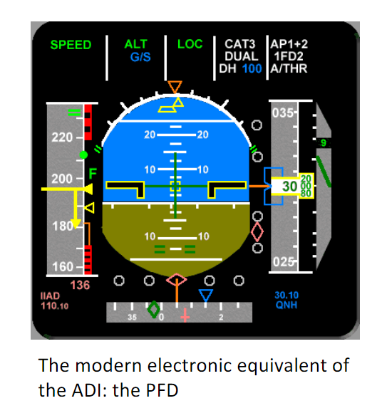
The PFD (Primary Flight Display) displays virtually all of the information that the pilot requires to determine basic flight parameters (altitude, attitude, airspeed, rate of climb, heading, etc) plus autopilot and auto-throttle engagement status, flight director modes and approach status.
It replaces the old mechanical ADI (Attitude Direction Indicator) and HSI (Horizontal Situation Indicator).
-
What is the ND of the EFIS? What does it display?
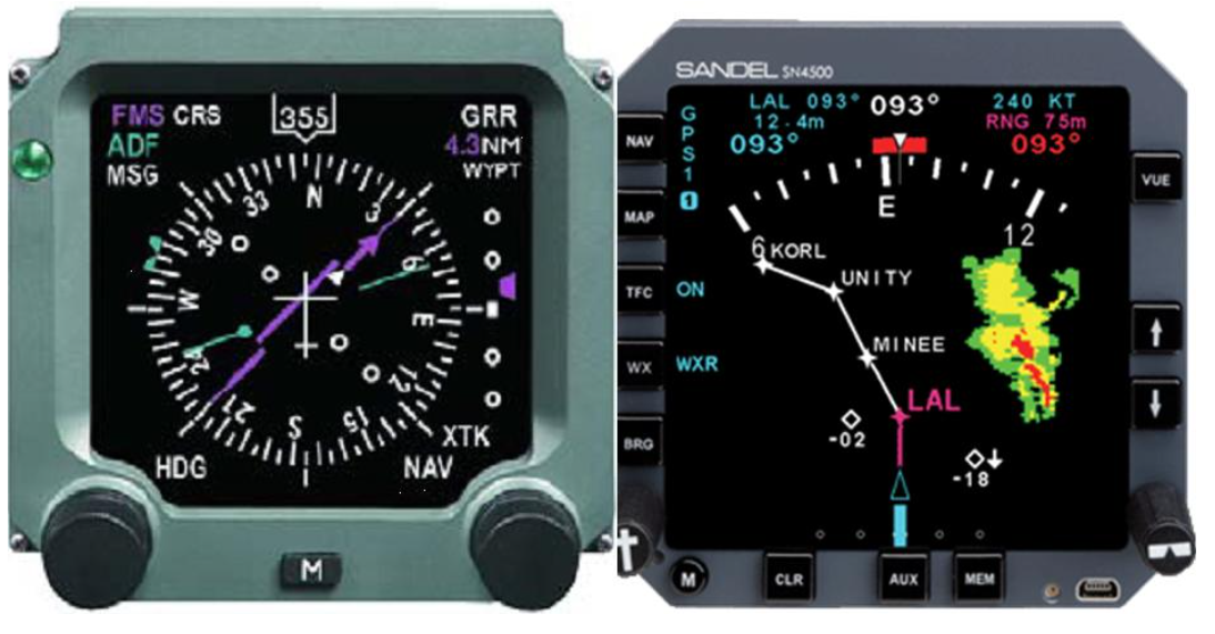
The navigation display (ND) replaces a number of different instruments found on a conventional aircraft instrument panel, mostly the Horizontal Situation Indicator (HSI), and may be used to depict some or all of the following information:
- heading flown;
- heading or track selected;
- bearing to or from a navigation beacon: VHF, VOR, DME;
- lateral deviation from a selected track;
- ground speed, distance and time to go;
- aeronautical map;
- weather information;
There are different designs, compass mode which replaces the old HSI and map mode provides intuitive information about the lateral flight status.
-
What is the HUD?
In a Head Up Display a computer-generated image is superimposed on a pilot’s normal view, through the windshield, of the terrain ahead.
-
How was information displayed in the old days of aviation? What was the disadvantage of electro-mechanical indicators?
The primary flight status information was structured first in a basic ‘six’arrangement and later in a basic ‘T’ arrangement. These arrangements allowed for various efficient scanning patterns depending on the phase of flight.Limited flight information was presented on electro-mechanicaldials and gauges. The main disadvantage of these dials and gauges is that it isdifficult and mechanically complex to integrate multiple sources of informationonto a single indicator. Therefore, a classic cockpit had an abundance ofindicators, which led to high workload and low flight-technical performance.
-
Describe in detail the three main components of a Flight Management System.
What are the functions of these three components of the FMS?
Flight Management Computer (FMC): This is the core of the FMS. It processes flight plan data, performs calculations for navigation and flight planning, and provides essential flight information to the pilots.
Flight Data Storage Unit (FDSU): This unit is responsible for storing critical flight data. It has a database of waypoints, radio navaids, airports, airways.
Command/Display Unit (CDU): This is the primary interface between the pilots and the FMS. Pilots use the CDU to input flight plans, make changes to the flight route, and monitor various aspects of the flight.
-
What are the three general functions of the FMS? Explain how the three
FMS components are used to serve these functions
Flight Planning: The FMS provides a computerized flight planning aid to the pilot, primarily through the Command/Display Unit (CDU). This function allows for the creation, modification, and management of the flight plan.
Navigation and Guidance: The FMS combines data from various navigation sources (such as INS, GPS, navaids) to derive the best estimate of the aircraft's position and velocity. It then provides both lateral (LNAV) and vertical (VNAV) guidance to the flight control systems, such as the autopilot or flight director.
Optimization and Performance Prediction: The FMS optimizes the flight plan by selecting the appropriate speed, altitude, and engine power settings during all phases of flight. It integrates knowledge about aircraft type and weight, fuel weight, engine type, performance characteristics, and other relevant factors.
-
Why is the name ‘accelerometer’ regarded to be a misnomer? In other words, what does it actually measure?
An accelerometer measures the specific force and not the true acceleration of the vehicle f = a - g
-
What is the accelerometer’s main inaccuracy called and how does it propagate to a distance error with respect to time?
The main error in accelerometers is called the accelerometer bias. This error is often unknown and it changes in time. The bias of an accelerometer results in an erroneous specific force measurement, which is carried out in the distance calculation. This can result in erroneous corrections for transport wander.
-
What are the two types of accelerometers? What is their main difference?
Stable Platform and Strapdown INS. Stable platform measures in Geodetic ref frame and strapdown INS in Body ref frame.
-
What are the advantages and disadvantages of Stable Platform and Strapdown INS?
Stable platform measures directly in navigation ref frame, but relies on mechanical gyros (high maintenance cost, mechanically complex,...).
Strapdown relies on ring laser gyros (RLG) and are much more accurate and reliable, but also makes strapdown INS expensive (initial cost) and does not measure in geodetic ref frame, which then needs a transformation. Both need corrections for transport wander and apparent drift.
-
In a strapdown INS accelerometers are used together with optical gyroscopes. How many accelerometers and optical gyroscopes are used in such a navigation system? What do they measure? And in what reference frame?
Three accelerometers and three gyroscopes. Accelerometers measure the specific force in the three axes (ax, ay, az) while gyroscope the angular rate (p, q, r). Both measure in body axes, because they are strapped to the vehicle
-
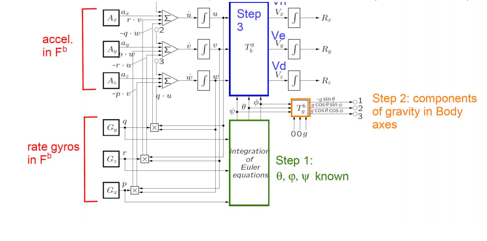
Describe the 4 consecutive computation steps (and in the correct order!) of an analytic platform in which optical gyroscopes and accelerometers are used together to derive the navigation solution.
1- Integration of the Euler Equations
2- Resolution of the gravity vector
3- Integration of the vehicle dynamics of motion
4- Computation of the navigation solutions
-
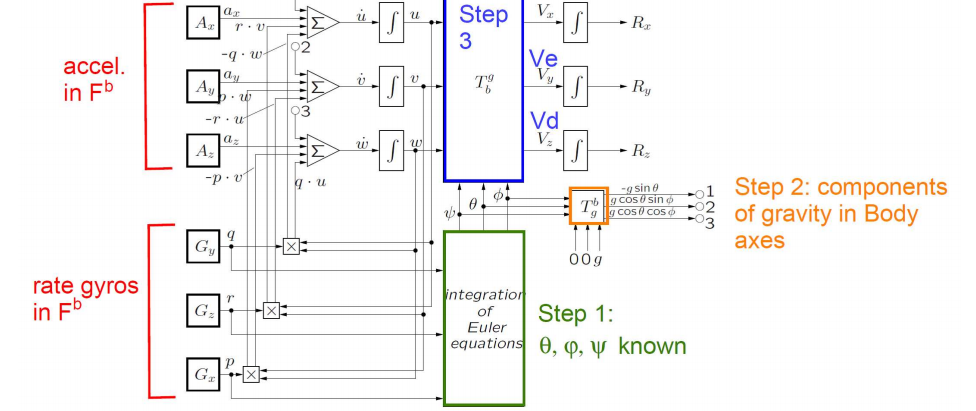
Why are the calculations in a strapdown INS being executed in a specific order?
Everything is measured in Body frame, but for navigation we need to get a navigation solution in Geodetic frame. Because the accelerometer measures the specific force, the true aircraft accel. is obtained by adding gravity components (in Body) to measurements. Resolution of gravity vector means that gravity, defined in Geodetic frame, needs to be transformed to Body frame first before adding it to the accel. measurements. The final result needs to be transformed in Geodetic frame to be used for navigation
-
To make a stable-platform INS work, Schuler tuning is required. Describe what “Schuler tuning” is and why this is considered an advantage for the propagation of accelerometer sensor inaccuracies?
Schuler tuning in a stable-platform INS is not actually a process of "tuning" in the traditional sense. It refers to an undamped closed-loop corrective action that constrains the system's tilt errors. This action makes the platform behave like a Schuler pendulum, allowing it to oscillate about a zero value with an 84.4-minute period. Schuler tuning is achieved by feeding back the accelerometer-derived vehicle rate turns to torque the vertical gyro. This ensures that the platform follows the local vertical as the aircraft moves over the spherical Earth, thereby correcting for transport wander.
-
Is Schuler tuning also present in analytic platforms? Briefly explain your answer.
YES In strapdown INS systems, which use a virtual or analytic platform, Schuler tuning is also present. This setup maintains a "virtual" platform that exhibits the same characteristics, including Schuler oscillations, as a gimballed stable platform.
-
Describe the main working principle of the VHF Omni-directional
Range (VOR) beacon. Include in your answer the REF and VAR signals
used for navigation, the airborne receiver, and how the VOR information is
presented to the pilot.
The VOR principle of operation is bearing measurement by phase comparison. The transmitter on the ground produces and transmits a carrier signal
composed of two sub carriers that amplitude and frequency modulate the carrier at 30 Hz, respectively. The phase of modulation for one sub carrier is omnidirectional (the REF signal), while the phase of modulation of the other sub carrier (the VAR signal) depends on the direction relative to the ground station. The AM and FM signals are constructed in such a way that they are in phase (0 phase difference) in the direction of the Magnetic North. The airborne receiver tunes into the carrier frequency and filters out the AM and FM sub signals. Comparing the phase between the REF and the VAR shows what radial the aircraft is on. The radial info is displayed on the HSI.
-
What type of information does the VOR carry?
Radial the aircraft is on, morse code for identification, voice
-
Describe the main working principle of the Doppler VHF Omni-directional Range (DVOR) beacon.
The DVOR has an omnidirectional antenna in the center that sends out a carrier was which is amplitude modulated with a 30Hz sinusoidal. This is the REF signal. Surrounding the central transmitter is an array of placed on a circular track. These antennas are "electronically rotated" at a speed of 30 revolutions per second. This creates a Doppler shift of the carrier frequency, observable by a distant observer. The Doppler effect causes the subcarrier to be modulated by FM modulation.The airborne receiver receives both signals, demodulates them and compares the phase difference between the demodulated REF and VAR signals. This comparison is interpreted as the radial from the station.
-
A DVOR suffers from a so-called switching frequency. Explain how the switching frequency is caused, why it is considered a handicap for VOR
receivers, and how it is mitigated.
Switching frequency is caused by the antennas placed in the circular array that
each transmit in turn. This discrete switching causes will appear in
the frequency spectrum as spurious side bands that distort the signals used for
navigation. To mitigate this, adjacent antennas to the transmitting
antenna will also transmit the signal, but at a lower power. This will reduce
the power of the spurious side bands in the frequency spectrum
-
How does the DME system work?
DME operates by sending a pulsed signal from the aircraft to the DME ground station, which then after 50 microseconds transmits a reply. The time delay between the interrogation and reply is measured by the airborne equipment, and this delay is converted into distance.DME measures the slant range, not the horizontal distance.DME has various modes of operation, including search, track, and hold modes.DME provides high accuracy, typically within 0.1 nautical miles.
-
Explain how the aircraft equipment can distinguish between replies of the DME station to other aircraft and the replies of the DME station to your own aircraft.
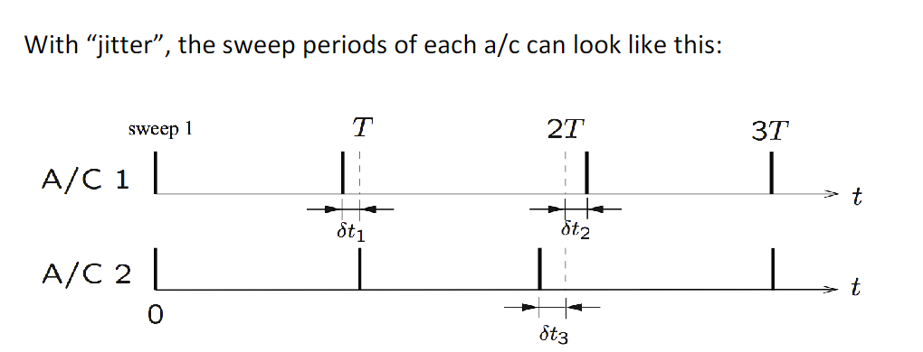
The airborne equipment distinguishes between replies to its own interrogations and those to other aircraft by using a random pulse spacing in its interrogation signal called "jitter". The sweep periods are random for each aircraft. Thatis, the sweeps have a period of T ± δt, where δt is small and random.
-
Describe the three main components of an ILS system, and make a sketch
indicating where these components are positioned with respect to the runway.
- Glideslope antenna for vertical guidance, located at the runway threshold.
- Localizer antenna for horizontal guidance, located at the back of the runway
- Marker beacon or DME, located in front of the runway, that provides distance to the runway
-
Describe in general terms the antenna patterns generated by an ILS. How are
they used by the on-board equipment?
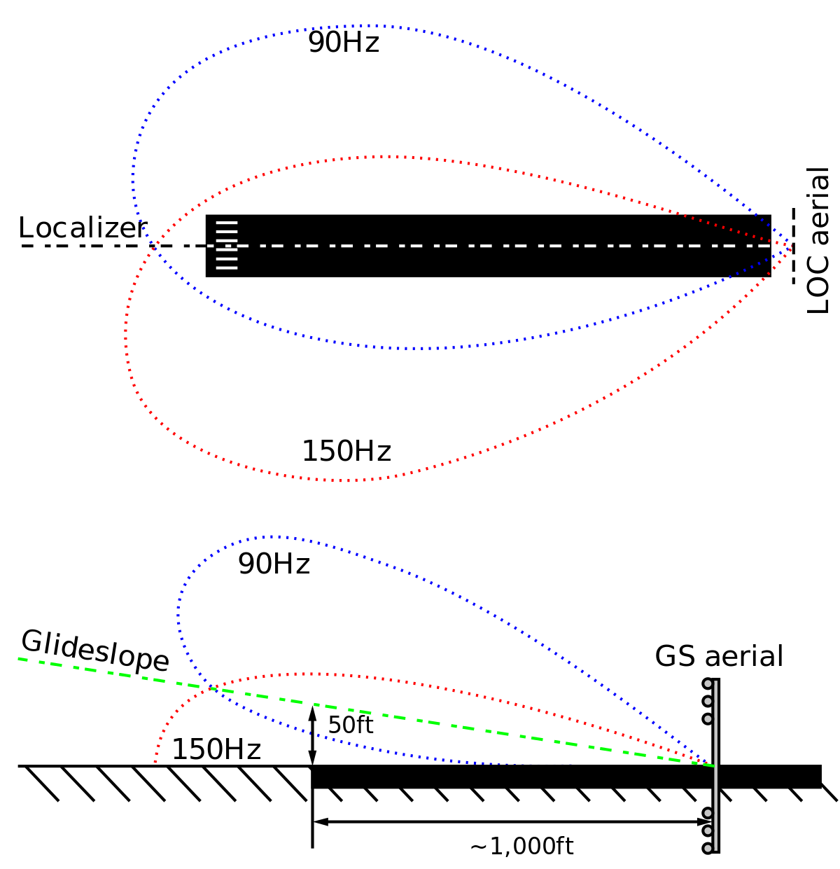
The ILS GS and LOC antennas generate lobe patterns that are received by the
airborne ILS receiver as either dominant 90 Hz or 150 Hz modulations.Where the two modulation signals are received equal in strength, there you will either find the glidepath or the runway centerline. When the airborne receiver receives the 90 Hz signal as the dominant signal, the pilot gets a ”fly-down” or ”fly-right” guidance. For the 150 Hz this is vice versa.
-
What is a ‘false glideslope’? At what elevation angle does it occur?
Because the ILS receiver is set to display ‘fly up’ at reception of the 150 Hz modulated signal and ‘fly down’ at the reception of the 90 Hz modulated signal, the ‘stable’ glide slope of 3 degrees is accompanied by another glide slope of 15 degrees.
-
Why can a conventional ILS installation only be used on flat terrain?
Because ILS relies on the multi-path effect, obstacles in terrain (other aircraft,
vehicles) can result in disturbances of the ILS signal.
-
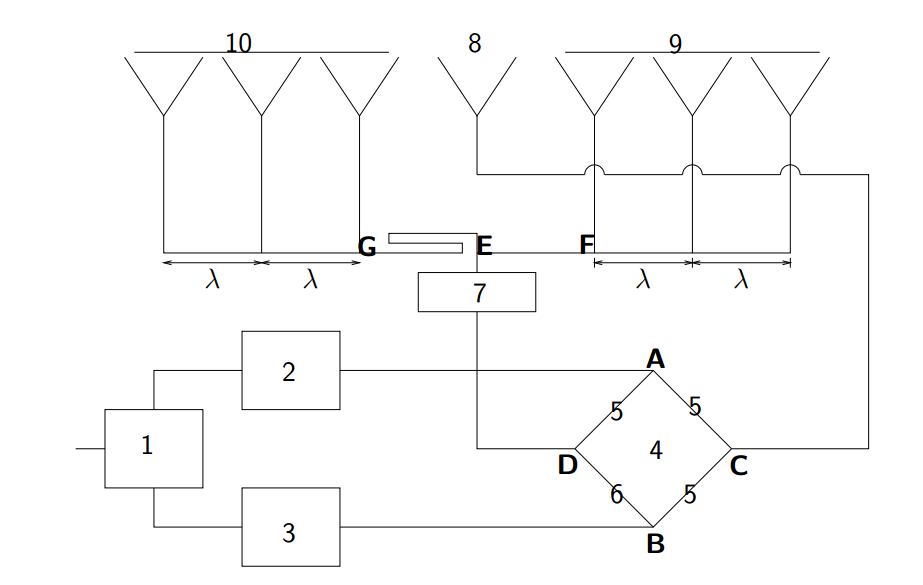
Looking at the figure explain the various steps of how the ILS localizer signals are modulated. What signals are sent by the central antenna, the left antenna and the right antenna?
1) Carrier wave2) and 3) signal is AM at 90Hz and 150Hz respectively4) This is the antenna bridge5) length 1/4 lambda6) length 3/4 lambda - it adds a phase of 180 degrees7) 90 degrees phase addition8) central antenna
9) right antenna
10) left antenna - has an additional 180 degree phase addition
-
How does GPS communication work? How can a receiver determine its position?
- Each GPS satellite has its own unique chip-sequence or key, known as a PRN (Pseudo-Random-Noise) identifier. Not the whole string is sent, only 1023 bits every 1 millisecond. All satellites can transmit on the same carrier frequency without interfering with each other due to these unique PRN codes.-The GPS receiver generates a copy of this signal
- The receiver then aligns its generated copy with the received signal through brute force cross-correlation computations.
- The receiver then applies a time-shift to its local copy to match the received signal. This measured time shift (travel time) is converted into a pseudo range, which is the estimated distance between the satellite and the receiver.
-
How many unknows need to be solved by a GPS receiver to determine its position?
To find an estimate for the position, the GPS receiver requires signals from at least four satellites. By solving the equations involving the pseudo ranges from these satellites, the receiver can calculate the 4 unknowns, the three-dimensional position (latitude, longitude, altitude) and the clock error.
-
Is GPS a sole means navigation system?
No! A sole means navigation system is defined as one that, for a given phase of flight, must meet all four navigation system performance requirements: accuracy, integrity, availability, and continuity of service. At the current state, GPS is typically used as a supplemental means navigation system, meaning it must be used in conjunction with a sole means navigation system. This is because, although GPS is highly accurate and reliable, it may not always meet the requirements for availability and continuity of service.
-
What are the three types of error in the Pseudo-Range calculated by the receiver?
- Receiver clock error (it's not an atomic clock)
- Satellite clock error: clock on board of the satellite ticks faster due to being further from Earth's mass.
- Signal propagation errors due to signal blocking, multipath effect, lower GDOP (when satellites are closer) and ionosphere interference.
-
Explain the concept of Differential GPS
The DGPS system requires a reference station located at a known location. The station also has a GPS receiver onboard which is used to estimate the station's position and then calculate the correction factors at that location.The station then broadcasts the calculated correction to all GPS users nearby, which in turn use the correct to improve the accuracy of their own estimated position.
-
Describe the basic working principle and the specific functions of all essential elements of a primary surveillance radar (PSR).
A PSR rotates while transmitting high frequency pulses which reflect off objects (such as aircraft) and return to the radar.
The radar broadcasts these pulses along a directional pattern called the beamdiwth which is narrow in azimuth (radial) and very broad in elevation.
To create the pulses, the radar has a RF switch that switches between a transmission and receiving mode.
The PSR uses pulse modulation. The transmission pattern is characterized by the pulse width, the rest time and the pulse repeat time.
-
What aircraft variables or states can be measured with the primary surveillance radar?
Slant Range: Distance from the radar to the aircraft, determined by the time it takes for the radar signal to return. R = c*t/2
Azimuth: Direction or angle of the aircraft relative to the radar, determined by the position of the radar's rotating antenna when the signal is received.
-
Describe in words how the rotational velocity of a PSR radar affects the radar range.
The rotation speed of the radar antenna determines the update rate of target information. Faster rotation can provide more frequent updates but reduce the radar range as there is not enough time for distant objects to be detected.
-
Describe in words how the pulse-repeat time of a PSR radar affects the maximum radar range.
If the time to repeat the pulse is too short, it cannot received the reflected pulses from distant objects.Rmax = c*PST/2
-
Describe in words how the pulse width of a radar affects the minimum radar range.
The minimum radar range is defined as: Rmin = c*PW/2
So for an object to be detected it should be at least half a pulse away from the radar.
-
Explain how the radar resolution of a PSR determines to a large extend the minimum separation distance between aircraft.
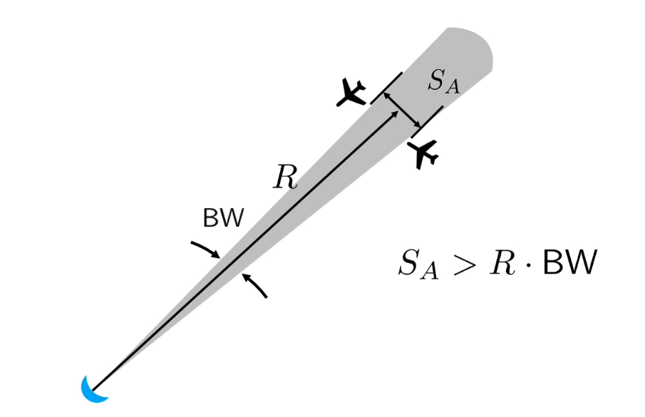
Two objects at the same bearing angle need to be separated by at least half a pulse width, to be able to be detected separately.
Furthermore, two objects at the same range need to be separated by more than the range times the beamdiwth to be detected as separate entities.
-
What other complementary radar system is often connected to the primary surveillance radar? What does this system measure?
Secondary Surveillance Radar (SSR): Often paired with PSR, SSR transmits interrogations to aircraft transponders, which respond with information such as altitude and identification. This system provides additional data not available with PSR alone.
-
Describe the two modes of an SSR. How many codes can be selected in mode A?
- Mode A: In this mode, the interrogation interval between pulses P1 and P3 is 8μs. The transponder replies with the Aircraft Identification Code (ACID), which is defined by Air Traffic Control (ATC) and set by the pilot on the transponder cockpit interface. This mode utilizes 12 bits, allowing for 2^12 =(4096) different ACID codes.
- Mode C: In this mode, the interrogation interval between pulses P1 and P3 is 21μs. The transponder replies with the aircraft's pressure altitude in steps of 100 feet (QNE), essentially providing the aircraft's flight level (FL).
-
Describe the interrogation/reply process of an SSR and an aircraft transponder. How does the transponder know what reply it should give?
The interrogation signal consists of three pulses (P1, P2, P3). The transponder knows which reply to give based on the positioning of these pulses. (8 μs or 21 μs)
-
Describe the phenomenon of side-lobe interrogation. How is this problem solved for the SSR?
There is a second, omnidirectional, pulse between P1 and P3, the P2 pulse. The signal strength of this pulse is higher than (encompasses) the sidelobes. The issue is resolved by ensuring that the transponder only replies when P1 and P3 pulses are > 9 dB larger than P2, a situation that occurs only in the main lobes of the antenna.
-
The SSRS can be upgraded with Mode S. What is Mode S and what primary virtue does it have with respect to the 'old' system?
SSR Mode S permits discrete addressing of aircraft: a unique 24-bitMode S address is assigned to each aircraft so that aircraft can beunambiguously identified and addressed worldwide: 2^24 ≈ 17 million.
-
How is information extracted from the transponder reply signal?
The reply from the transponder consists of twelve data pulses. These pulses are uniformly spaced between two framing pulses.Each pulse has a different length, that is then translated to a fixed number. Adding the numbers together yields the ID code or the pressure altitude. Maximum of 2^12 codes can be transmitted.
-
How is the airspace organized? What are the names of the different zones and where are they located?
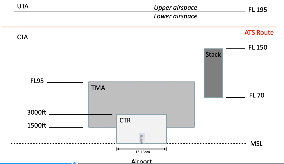
- Control Zone (CTR) located around the airport. Usually a circular area. Aircrafts here speak with Tower Control (TWR)- Terminal Control Area (TMA): Approach/Departure, incoming and outgoing flights between CTR and CTA. Here they speak with Approach (APP)- Control Area (CTA): General ATC, within the FIR and below FL195 (lower airspace). Here aircrafts are handed over to Area Control (ACC)
- Upper Control Area (UTA): across FIRs and above FL195. This zone is controlled by Eurocontrol. In the Netherlands the UTA is called Maastricht.
-
What does the acronym STAR and SID indicate?
Standard Terminal Arrival Route and Standard Instrument Departure
-
What is RNAV? Explain the difference between RNAV and standard navigation.
It stands for Area Navigation. It is a method of instrument flight rules (IFR) navigation that enables aircraft to fly on any desired path within the network of navigational beacons, rather than being restricted to flying directly to or from the beacons. A comparison follows below.Standard Navigation: The pilot must navigate leg by leg from VOR to VOR, which can lead to a longer, less efficient path.
RNAV: The pilot follows a pre-programmed, optimal route that directly connects A to B, without being constrained by the locations of ground-based beacons.
-
What is ACAS? What is TCAS?
Airborne Collision Avoidance System. It works as a last resort fall back option to prevent mid-air collisions when ATC separation has failed. TCAS is the most used form of ACAS.
-
How does ACAS work?
ACAS works by means of aircraft interrogating each other’s SSR and requires
distance, distance-rate, and altitude as the critical parameters to detect conflicts. The distance is obtained from the onboard SSR interrogations (round-trip of interrogation-reply cycle), the velocity by sending pulses after 1 second. The ratio distance / distance-rate results in a time measure that represents the time-to-collision. The SSR Mode C of the SSR allows the ‘aircraft’ to obtain the altitude of other aircraft and this information.
-
What information does TCAS provide to the pilot?
Traffic Advisory: 40s before CPA, shows altitude, bearing and range of intruder.Resolution Advisory: 25s before CPA shows the vertical escape manoeuvre to avoid a collision.
-
What are the two main problems with current ACAS systems?
Nuisance warnings (false alerts) and the they only provide vertical escape manoeuvres.

