2024-07-21T21:46:34+03:00[Europe/Moscow] en true <p>Conductor resistance causes a(n) ? between the voltage source and the connected</p><p>load.</p><p>a.</p><p>decrease in current</p><p>b.</p><p>power loss</p><p>c.</p><p>voltage drop</p><p>d.</p><p>all of the above</p>, <p>The NEC recommends that voltage drops on branch circuits not exceeding ? at the</p><p>farthest outlet of power, for heating or lighting loads, will provide for reasonable</p><p>efficiency of operation.</p><p>a.</p><p>2%</p><p>b.</p><p>3%</p><p>c.</p><p>4%</p><p>d.</p><p>5%</p>, <p>Loads are normally connected in ? with the source, and the resistance of the line is in</p><p> ? with the source.</p><p>a.</p><p>parallel / parallel</p><p>b.</p><p>parallel / series</p><p>c.</p><p>series / parallel</p><p>d.</p><p>series / series</p>, <p>If a generator voltage is 240 volts, and the load voltage is 235 volts, how much voltage</p><p>is dropped on the line?</p><p>Answer:</p>, <p>What is the percentage of voltage drop if you have 235 volts at a load fed from a 240-</p><p>volt source? (Round the FINAL answer to one decimal place.)</p><p>Answer:</p><p>%</p>, <p>Two rows of fluorescent lamps are installed in an office on the same branch circuit, with</p><p>each row drawing 12.5 amperes. The source voltage is 277 volts, and the total line</p><p>resistance of the circuit conductors is 0.5 Ω. The wire used has a constant (k) of 12.6.</p><p>What is the voltage at the load? (Round the FINAL answer to one decimal place.)</p><p>Answer:</p>, <p>Two rows of fluorescent lamps are installed in an office on the same branch circuit, with</p><p>each row drawing 12.5 amperes. The source voltage is 277 volts, and the total line</p><p>resistance of the circuit conductors is 0.5 Ω. The wire used has a constant (k) of 12.6.</p><p>What is the percentage of voltage drop? (Round the FINAL answer to one decimal place.)</p><p>Answer:</p><p>%</p>, <p>Two rows of fluorescent lamps are installed in an office on the same branch circuit, with</p><p>each row drawing 12.5 amperes. The source voltage is 277 volts, and the line resistance</p><p>is 0.5 Ω. The wire used has a constant (k) of 12.6. The voltage drop will be within the</p><p>recommendation of the NEC.</p><p>Select one:</p><p>True</p><p>False</p>, <p>How could you correct a voltage drop problem involving two rows of fluorescent fixtures</p><p>fed from the same circuit in a practical manner?</p><p>I. Change the fluorescent fixtures to incandescent light fixtures.</p><p>II. Install a lighting panel closer to the fixtures.</p><p>III. Install larger wire.</p><p>IV. Put each row of fixtures on a separate circuit.</p><p>a.</p><p>I. or II.</p><p>b.</p><p>I. or III.</p><p>c.</p><p>II. or III.</p><p>d.</p><p>III. or IV.</p>, <p>Two rows of fluorescent lamps are installed in an office on the same branch circuit, with</p><p>each row drawing 12.5 amperes. The source voltage is 277 volts, and the line resistance</p><p>is 0.5 Ω. The wire used has a constant (k) of 12.6. If the load is 129 feet from the source,</p><p>what is the specific wire size used in this installation? (Assume 75°C wire.)</p><p>Wire size = ____ AWG</p><p>Answer:</p>, <p>Two rows of fluorescent lamps are installed in an office on the same branch circuit, with</p><p>each row drawing 12.5 amperes. The source voltage is 277 volts, and the line resistance</p><p>is 0.5 Ω. The wire used has a constant (k) of 12.6. If the load is 130 feet from the source,</p><p>what size wire would you need to install for this circuit to meet the recommendations of</p><p>the NEC for acceptable voltage drop on a branch circuit? (Assume 75°C wire)</p><p>Wire size = ____ AWG</p><p>Answer:</p>, <p>A motor was overheating because of low voltage at its terminals. A transformer was</p><p>installed to correct the problem. What is the secondary voltage of the transformer</p><p>required to be in order to supply 240 volts to the motor? (Round the FINAL answer to one</p><p>decimal place.)</p><p>Answer:</p>, <p>Use the diagram to determine total resistance. (Round the FINAL answer to one decimal</p><p>place.) Note: Use the rated voltage and wattage to determine resistance.</p><p>Note: Ra and Rb represent the resistance of the wire. The 120 volts of the motor and</p><p>lamps is their rated voltage and not the actual voltage.</p><p>Answer:</p>, <p>Use the diagram to determine total current. (Round the FINAL answer to one decimal</p><p>place.)</p><p>Note: Ra and Rb represent the resistance of the wire. The 120 volts of the motor and</p><p>lamps is their rated voltage and not the actual voltage.</p><p>Answer:</p>, <p>Use the diagram to determine the voltage drop of the conductors. (Round the FINAL</p><p>answer to two decimal places.)</p><p>Note: Ra and Rb represent the resistance of the wire. The 120 volts of the motor and</p><p>lamps is their rated voltage and not the actual voltage.</p><p>Answer:</p>, <p>Use the diagram to determine the voltage at the load after calculating the voltage drop</p><p>of the wire.</p><p>Note: Ra and Rb represent the resistance of the wire. The 120 volts of the motor and</p><p>lamps is their rated voltage and not the actual voltage.</p><p>a.</p><p>115.34 V</p><p>b.</p><p>117.67 V</p><p>c.</p><p>120 V</p><p>d.</p><p>122.33 V</p>, <p>Use the diagram to determine the power loss in the conductors. (Round the FINAL</p><p>answer to two decimal places.)</p><p>Note: Ra and Rb represent the resistance of the wire. The 120 volts of the motor and</p><p>lamps is their rated voltage and not the actual voltage.</p><p>Answer:</p>, <p>Use the diagram to determine the current of the motor. (Round the FINAL answer to two</p><p>decimal places.)</p><p>Note: Ra and Rb represent the resistance of the wire. The 120 volts of the motor and</p><p>lamps is their rated voltage and not the actual voltage.</p><p>Answer:</p>, <p>Use the diagram to determine the current of each 100 W lamp. (Round the FINAL answer</p><p>to three decimal places.)</p><p>Note: Ra and Rb represent the resistance of the wire. The 120 volts of the motor and</p><p>lamps is their rated voltage and not the actual voltage.</p><p>Answer:</p>, <p>Use the diagram to determine the current of the 75 W lamp. (Round the FINAL answer to</p><p>three decimal places.)</p><p>Note: Ra and Rb represent the resistance of the wire. The 120 volts of the motor and</p><p>lamps is their rated voltage and not the actual voltage.</p><p>Answer:</p>, <p>Use the diagram to determine the total current of the loads. (Round the FINAL answer to</p><p>one decimal place.)</p><p>Note: Ra and Rb represent the resistance of the wire. The 120 volts of the motor and</p><p>lamps is their rated voltage and not the actual voltage.</p><p>Answer:</p>, <p>In a parallel circuit, the total current equals the sum of the current of the loads.</p><p>Select one:</p><p>True</p><p>False</p>, <p>Use the diagram to determine the total power consumed by the circuit.</p><p>Note: Ra and Rb represent the resistance of the wire. The 120 volts of the motor and</p><p>lamps is their rated voltage and not the actual voltage.</p><p>Answer:</p>, <p>Use the diagram to determine the power consumed by the motor. (Round the FINAL</p><p>answer to one decimal place.)</p><p>Note: Ra and Rb represent the resistance of the wire. The 120 volts of the motor and</p><p>lamps is their rated voltage and not the actual voltage.</p><p>Answer:</p>, <p>Use the diagram to determine the power consumed by each of the 100 W lamps. (Round</p><p>the FINAL answer to the nearest whole number.)</p><p>Note: Ra and Rb represent the resistance of the wire. The 120 volts of the motor and</p><p>lamps is their rated voltage and not the actual voltage.</p><p>Answer:</p>, <p>Use the diagram to determine the power consumed by the 75 W lamp. (Round the FINAL</p><p>answer to one decimal place.)</p><p>Note: Ra and Rb represent the resistance of the wire. The 120 volts of the motor and</p><p>lamps is their rated voltage and not the actual voltage.</p><p>Answer:</p>, <p>Use the diagram to determine the power consumed by the loads.</p><p>Note: Ra and Rb represent the resistance of the wire. The 120 volts of the motor and</p><p>lamps is their rated voltage and not the actual voltage.</p><p>Answer:</p>, <p>The total power consumed by the circuit is equal to the power consumed by the loads.</p><p>Note: Ra and Rb represent the resistance of the wire. The 120 volts of the motor and</p><p>lamps is their rated voltage and not the actual voltage.</p><p>Select one:</p><p>True</p><p>False</p>, <p>Use the diagram to determine the voltage across the load when the push button is</p><p>depressed. (Round the FINAL answer to one decimal place.)</p><p>Note: All voltage sources contain internal resistance that is usually ignored in</p><p>calculations because the resistive value of the load is so much greater than the</p><p>resistance of the source. This is not always the case. (Rb represents the battery's internal</p><p>resistance.)</p><p>Answer:</p>, <p>What would the current flow be if a short circuit is put across the battery's terminals?</p><p>Note: All voltage sources contain internal resistance that is usually ignored in</p><p>calculations because the resistive value of the load is so much greater than the</p><p>resistance of the source. This is not always the case. (Rb represents the battery's internal</p><p>resistance.)</p><p>Answer:</p>, <p>How much power is consumed by the load under short-circuit conditions?</p><p>Note: All voltage sources contain internal resistance that is usually ignored in</p><p>calculations because the resistive value of the load is so much greater than the</p><p>resistance of the source. This is not always the case. (Rb represents the battery's internal</p><p>resistance.)</p><p>Answer:</p>, <p>When the battery terminals are open, how much power is consumed by the load?</p><p>Answer:</p>, <p>Use the diagram to determine the power consumed by the motor when the push button</p><p>is depressed. (Round the FINAL answer to the nearest whole number.)</p><p>Answer:</p>, <p>Use the diagram to determine the power consumed by the motor when the push button</p><p>is depressed. (Round the FINAL answer to the nearest whole number.)</p><p>Note: All voltage sources contain internal resistance that is usually ignored in</p><p>calculations because the resistive value of the load is so much greater than the</p><p>resistance of the source. This is not always the case. (Rb represents the battery's internal</p><p>resistance.)</p><p>Answer:</p>, <p>Use the diagram to determine the power consumed by the motor when the push button</p><p>is depressed. (Round the FINAL answer to the nearest whole number.)</p><p>Note: All voltage sources contain internal resistance that is usually ignored in</p><p>calculations because the resistive value of the load is so much greater than the</p><p>resistance of the source. This is not always the case. (Rb represents the battery's internal</p><p>resistance.)</p><p>Answer:</p>, <p>Use the diagram to determine the power consumed by the motor when the push button</p><p>is depressed. (Round the FINAL answer to the nearest whole number.)</p><p>Note: All voltage sources contain internal resistance that is usually ignored in</p><p>calculations because the resistive value of the load is so much greater than the</p><p>resistance of the source. This is not always the case. (Rb represents the battery's internal</p><p>resistance.)</p><p>Answer:</p>, <p>Use the diagram to determine the power consumed by the motor when the push button</p><p>is depressed. (Round the FINAL answer to one decimal place.)</p><p>Note: All voltage sources contain internal resistance that is usually ignored in</p><p>calculations because the resistive value of the load is so much greater than the</p><p>resistance of the source. This is not always the case. (Rb represents the battery's internal</p><p>resistance.)</p><p>Answer:</p>, <p>What is the value of RL when the wattage is at peak?</p><p>a.</p><p>0.01 Ω</p><p>b.</p><p>0.25 Ω</p><p>c.</p><p>0.05 Ω</p><p>d.</p><p>1.00 Ω</p>, <p>Use the diagram to determine the voltage drop across the resistor R. (Round the FINAL</p><p>answer to two decimal places.)</p><p>Answer:</p>, <p>Use the diagram to determine the voltage drop across load M. (Round the FINAL answer</p><p>to two decimal places.)</p><p>Answer:</p>, <p>Use the diagram to determine the voltage drop across load L. (Round the FINAL answer</p><p>to two decimal places.)</p><p>Answer:</p> flashcards
AC Systems Lesson 4

AC Systems Lesson 4

  • Conductor resistance causes a(n) ? between the voltage source and the connected

    load.

    a.

    decrease in current

    b.

    power loss

    c.

    voltage drop

    d.

    all of the above

    The correct answer is: all of the above

  • The NEC recommends that voltage drops on branch circuits not exceeding ? at the

    farthest outlet of power, for heating or lighting loads, will provide for reasonable

    efficiency of operation.

    a.

    2%

    b.

    3%

    c.

    4%

    d.

    5%

    The correct answer is: 3%

  • Loads are normally connected in ? with the source, and the resistance of the line is in

    ? with the source.

    a.

    parallel / parallel

    b.

    parallel / series

    c.

    series / parallel

    d.

    series / series

    The correct answer is: parallel / series

  • If a generator voltage is 240 volts, and the load voltage is 235 volts, how much voltage

    is dropped on the line?

    Answer:

    The correct answer is: 5 V

  • What is the percentage of voltage drop if you have 235 volts at a load fed from a 240-

    volt source? (Round the FINAL answer to one decimal place.)

    Answer:

    %

    The correct answer is: 2.1

  • Two rows of fluorescent lamps are installed in an office on the same branch circuit, with

    each row drawing 12.5 amperes. The source voltage is 277 volts, and the total line

    resistance of the circuit conductors is 0.5 Ω. The wire used has a constant (k) of 12.6.

    What is the voltage at the load? (Round the FINAL answer to one decimal place.)

    Answer:

    The correct answer is: 264.5 V

  • Two rows of fluorescent lamps are installed in an office on the same branch circuit, with

    each row drawing 12.5 amperes. The source voltage is 277 volts, and the total line

    resistance of the circuit conductors is 0.5 Ω. The wire used has a constant (k) of 12.6.

    What is the percentage of voltage drop? (Round the FINAL answer to one decimal place.)

    Answer:

    %

    The correct answer is: 4.5

  • Two rows of fluorescent lamps are installed in an office on the same branch circuit, with

    each row drawing 12.5 amperes. The source voltage is 277 volts, and the line resistance

    is 0.5 Ω. The wire used has a constant (k) of 12.6. The voltage drop will be within the

    recommendation of the NEC.

    Select one:

    True

    False

    The correct answer is 'False'.

  • How could you correct a voltage drop problem involving two rows of fluorescent fixtures

    fed from the same circuit in a practical manner?

    I. Change the fluorescent fixtures to incandescent light fixtures.

    II. Install a lighting panel closer to the fixtures.

    III. Install larger wire.

    IV. Put each row of fixtures on a separate circuit.

    a.

    I. or II.

    b.

    I. or III.

    c.

    II. or III.

    d.

    III. or IV.

    The correct answer is: III. or IV.

  • Two rows of fluorescent lamps are installed in an office on the same branch circuit, with

    each row drawing 12.5 amperes. The source voltage is 277 volts, and the line resistance

    is 0.5 Ω. The wire used has a constant (k) of 12.6. If the load is 129 feet from the source,

    what is the specific wire size used in this installation? (Assume 75°C wire.)

    Wire size = ____ AWG

    Answer:

    The correct answer is: 12

  • Two rows of fluorescent lamps are installed in an office on the same branch circuit, with

    each row drawing 12.5 amperes. The source voltage is 277 volts, and the line resistance

    is 0.5 Ω. The wire used has a constant (k) of 12.6. If the load is 130 feet from the source,

    what size wire would you need to install for this circuit to meet the recommendations of

    the NEC for acceptable voltage drop on a branch circuit? (Assume 75°C wire)

    Wire size = ____ AWG

    Answer:

    The correct answer is: 10

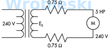
  • A motor was overheating because of low voltage at its terminals. A transformer wasinstalled to correct the problem. What is the secondary voltage of the transformerrequired to be in order to supply 240 volts to the motor? (Round the FINAL answer to onedecimal place.)Answer:

    A motor was overheating because of low voltage at its terminals. A transformer was

    installed to correct the problem. What is the secondary voltage of the transformer

    required to be in order to supply 240 volts to the motor? (Round the FINAL answer to one

    decimal place.)

    Answer:

    The correct answer is: 263.3 V

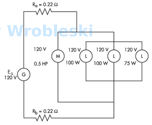
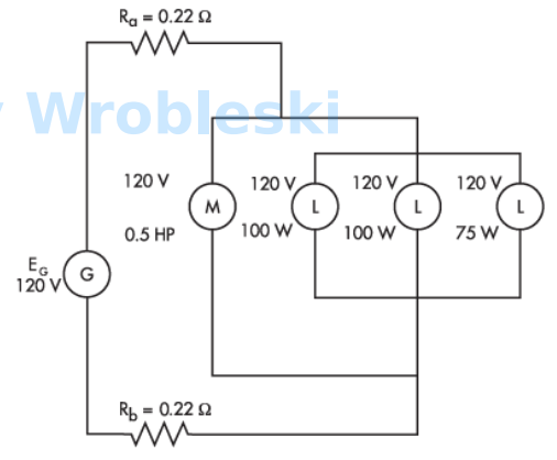
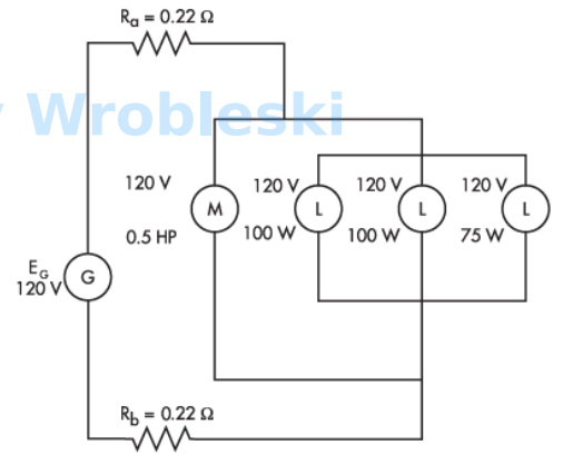
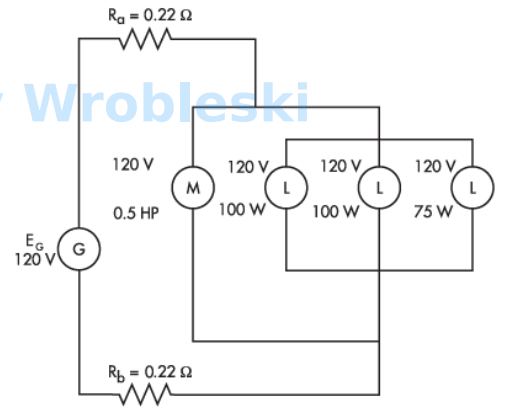
  • Use the diagram to determine total resistance. (Round the FINAL answer to one decimalplace.) Note: Use the rated voltage and wattage to determine resistance.Note: Ra and Rb represent the resistance of the wire. The 120 volts of the motor andlamps is their rated voltage and not the actual voltage.Answer:

    Use the diagram to determine total resistance. (Round the FINAL answer to one decimal

    place.) Note: Use the rated voltage and wattage to determine resistance.

    Note: Ra and Rb represent the resistance of the wire. The 120 volts of the motor and

    lamps is their rated voltage and not the actual voltage.

    Answer:

    The correct answer is: 22.7 Ω

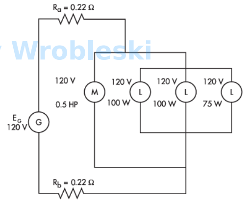
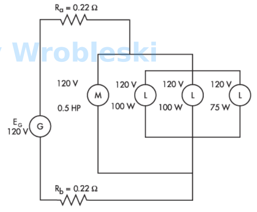
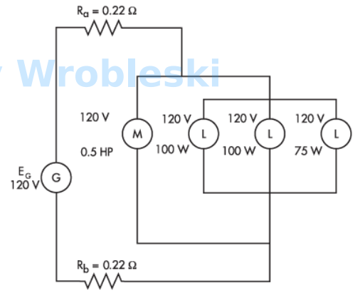
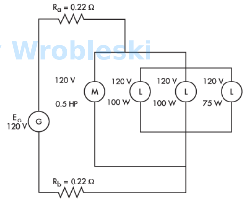
  • Use the diagram to determine total current. (Round the FINAL answer to one decimalplace.)Note: Ra and Rb represent the resistance of the wire. The 120 volts of the motor andlamps is their rated voltage and not the actual voltage.Answer:

    Use the diagram to determine total current. (Round the FINAL answer to one decimal

    place.)

    Note: Ra and Rb represent the resistance of the wire. The 120 volts of the motor and

    lamps is their rated voltage and not the actual voltage.

    Answer:

    The correct answer is: 5.3 A

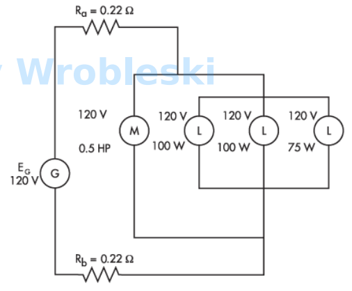
  • Use the diagram to determine the voltage drop of the conductors. (Round the FINALanswer to two decimal places.)Note: Ra and Rb represent the resistance of the wire. The 120 volts of the motor andlamps is their rated voltage and not the actual voltage.Answer:

    Use the diagram to determine the voltage drop of the conductors. (Round the FINAL

    answer to two decimal places.)

    Note: Ra and Rb represent the resistance of the wire. The 120 volts of the motor and

    lamps is their rated voltage and not the actual voltage.

    Answer:

    The correct answer is: 2.33 V

  • Use the diagram to determine the voltage at the load after calculating the voltage dropof the wire.Note: Ra and Rb represent the resistance of the wire. The 120 volts of the motor andlamps is their rated voltage and not the actual voltage.a.115.34 Vb.117.67 Vc.120 Vd.122.33 V

    Use the diagram to determine the voltage at the load after calculating the voltage drop

    of the wire.

    Note: Ra and Rb represent the resistance of the wire. The 120 volts of the motor and

    lamps is their rated voltage and not the actual voltage.

    a.

    115.34 V

    b.

    117.67 V

    c.

    120 V

    d.

    122.33 V

    The correct answer is: 117.67 V

  • Use the diagram to determine the power loss in the conductors. (Round the FINALanswer to two decimal places.)Note: Ra and Rb represent the resistance of the wire. The 120 volts of the motor andlamps is their rated voltage and not the actual voltage.Answer:

    Use the diagram to determine the power loss in the conductors. (Round the FINAL

    answer to two decimal places.)

    Note: Ra and Rb represent the resistance of the wire. The 120 volts of the motor and

    lamps is their rated voltage and not the actual voltage.

    Answer:

    The correct answer is: 12.36 W

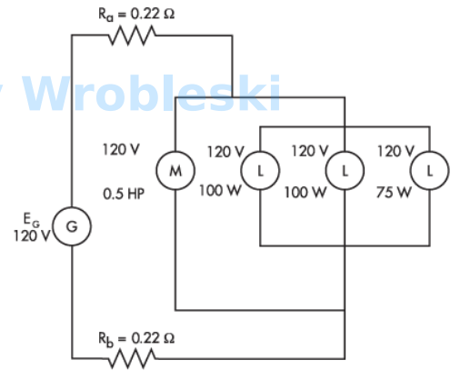
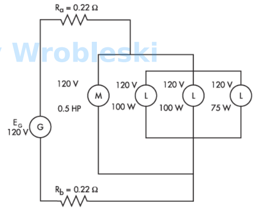
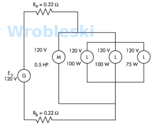
  • Use the diagram to determine the current of the motor. (Round the FINAL answer to twodecimal places.)Note: Ra and Rb represent the resistance of the wire. The 120 volts of the motor andlamps is their rated voltage and not the actual voltage.Answer:

    Use the diagram to determine the current of the motor. (Round the FINAL answer to two

    decimal places.)

    Note: Ra and Rb represent the resistance of the wire. The 120 volts of the motor and

    lamps is their rated voltage and not the actual voltage.

    Answer:

    The correct answer is: 3.05 A

  • Use the diagram to determine the current of each 100 W lamp. (Round the FINAL answerto three decimal places.)Note: Ra and Rb represent the resistance of the wire. The 120 volts of the motor andlamps is their rated voltage and not the actual voltage.Answer:

    Use the diagram to determine the current of each 100 W lamp. (Round the FINAL answer

    to three decimal places.)

    Note: Ra and Rb represent the resistance of the wire. The 120 volts of the motor and

    lamps is their rated voltage and not the actual voltage.

    Answer:

    The correct answer is: 0.817 A

  • Use the diagram to determine the current of the 75 W lamp. (Round the FINAL answer tothree decimal places.)Note: Ra and Rb represent the resistance of the wire. The 120 volts of the motor andlamps is their rated voltage and not the actual voltage.Answer:

    Use the diagram to determine the current of the 75 W lamp. (Round the FINAL answer to

    three decimal places.)

    Note: Ra and Rb represent the resistance of the wire. The 120 volts of the motor and

    lamps is their rated voltage and not the actual voltage.

    Answer:

    The correct answer is: 0.613 A

  • Use the diagram to determine the total current of the loads. (Round the FINAL answer toone decimal place.)Note: Ra and Rb represent the resistance of the wire. The 120 volts of the motor andlamps is their rated voltage and not the actual voltage.Answer:

    Use the diagram to determine the total current of the loads. (Round the FINAL answer to

    one decimal place.)

    Note: Ra and Rb represent the resistance of the wire. The 120 volts of the motor and

    lamps is their rated voltage and not the actual voltage.

    Answer:

    The correct answer is: 5.3 A

  • In a parallel circuit, the total current equals the sum of the current of the loads.

    Select one:

    True

    False

    The correct answer is 'True'.

  • Use the diagram to determine the total power consumed by the circuit.Note: Ra and Rb represent the resistance of the wire. The 120 volts of the motor andlamps is their rated voltage and not the actual voltage.Answer:

    Use the diagram to determine the total power consumed by the circuit.

    Note: Ra and Rb represent the resistance of the wire. The 120 volts of the motor and

    lamps is their rated voltage and not the actual voltage.

    Answer:

    The correct answer is: 636 W

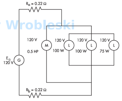
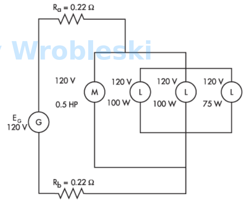
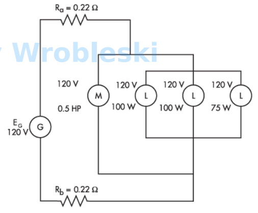
  • Use the diagram to determine the power consumed by the motor. (Round the FINALanswer to one decimal place.)Note: Ra and Rb represent the resistance of the wire. The 120 volts of the motor andlamps is their rated voltage and not the actual voltage.Answer:

    Use the diagram to determine the power consumed by the motor. (Round the FINAL

    answer to one decimal place.)

    Note: Ra and Rb represent the resistance of the wire. The 120 volts of the motor and

    lamps is their rated voltage and not the actual voltage.

    Answer:

    The correct answer is: 358.9 W

  • Use the diagram to determine the power consumed by each of the 100 W lamps. (Roundthe FINAL answer to the nearest whole number.)Note: Ra and Rb represent the resistance of the wire. The 120 volts of the motor andlamps is their rated voltage and not the actual voltage.Answer:

    Use the diagram to determine the power consumed by each of the 100 W lamps. (Round

    the FINAL answer to the nearest whole number.)

    Note: Ra and Rb represent the resistance of the wire. The 120 volts of the motor and

    lamps is their rated voltage and not the actual voltage.

    Answer:

    The correct answer is: 96 W

  • Use the diagram to determine the power consumed by the 75 W lamp. (Round the FINALanswer to one decimal place.)Note: Ra and Rb represent the resistance of the wire. The 120 volts of the motor andlamps is their rated voltage and not the actual voltage.Answer:

    Use the diagram to determine the power consumed by the 75 W lamp. (Round the FINAL

    answer to one decimal place.)

    Note: Ra and Rb represent the resistance of the wire. The 120 volts of the motor and

    lamps is their rated voltage and not the actual voltage.

    Answer:

    The correct answer is: 72.1 W

  • Use the diagram to determine the power consumed by the loads.Note: Ra and Rb represent the resistance of the wire. The 120 volts of the motor andlamps is their rated voltage and not the actual voltage.Answer:

    Use the diagram to determine the power consumed by the loads.

    Note: Ra and Rb represent the resistance of the wire. The 120 volts of the motor and

    lamps is their rated voltage and not the actual voltage.

    Answer:

    The correct answer is: 623 W

  • The total power consumed by the circuit is equal to the power consumed by the loads.Note: Ra and Rb represent the resistance of the wire. The 120 volts of the motor andlamps is their rated voltage and not the actual voltage.Select one:TrueFalse

    The total power consumed by the circuit is equal to the power consumed by the loads.

    Note: Ra and Rb represent the resistance of the wire. The 120 volts of the motor and

    lamps is their rated voltage and not the actual voltage.

    Select one:

    True

    False

    The correct answer is 'False'.

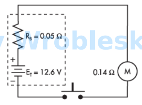
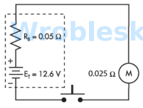
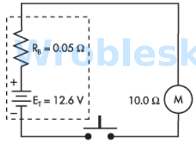
  • Use the diagram to determine the voltage across the load when the push button isdepressed. (Round the FINAL answer to one decimal place.)Note: All voltage sources contain internal resistance that is usually ignored incalculations because the resistive value of the load is so much greater than theresistance of the source. This is not always the case. (Rb represents the battery's internalresistance.)Answer:

    Use the diagram to determine the voltage across the load when the push button is

    depressed. (Round the FINAL answer to one decimal place.)

    Note: All voltage sources contain internal resistance that is usually ignored in

    calculations because the resistive value of the load is so much greater than the

    resistance of the source. This is not always the case. (Rb represents the battery's internal

    resistance.)

    Answer:

    The correct answer is: 9.3 V

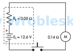
  • What would the current flow be if a short circuit is put across the battery's terminals?Note: All voltage sources contain internal resistance that is usually ignored incalculations because the resistive value of the load is so much greater than theresistance of the source. This is not always the case. (Rb represents the battery's internalresistance.)Answer:

    What would the current flow be if a short circuit is put across the battery's terminals?

    Note: All voltage sources contain internal resistance that is usually ignored in

    calculations because the resistive value of the load is so much greater than the

    resistance of the source. This is not always the case. (Rb represents the battery's internal

    resistance.)

    Answer:

    The correct answer is: 252 A

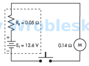
  • How much power is consumed by the load under short-circuit conditions?Note: All voltage sources contain internal resistance that is usually ignored incalculations because the resistive value of the load is so much greater than theresistance of the source. This is not always the case. (Rb represents the battery's internalresistance.)Answer:

    How much power is consumed by the load under short-circuit conditions?

    Note: All voltage sources contain internal resistance that is usually ignored in

    calculations because the resistive value of the load is so much greater than the

    resistance of the source. This is not always the case. (Rb represents the battery's internal

    resistance.)

    Answer:

    The correct answer is: 0 W

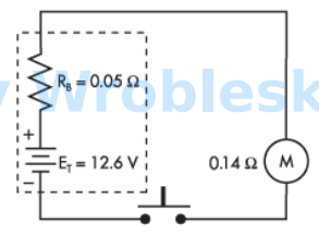
  • When the battery terminals are open, how much power is consumed by the load?Answer:

    When the battery terminals are open, how much power is consumed by the load?

    Answer:

    The correct answer is: 0 W

  • Use the diagram to determine the power consumed by the motor when the push buttonis depressed. (Round the FINAL answer to the nearest whole number.)Answer:

    Use the diagram to determine the power consumed by the motor when the push button

    is depressed. (Round the FINAL answer to the nearest whole number.)

    Answer:

    The correct answer is: 706 W

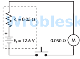
  • Use the diagram to determine the power consumed by the motor when the push buttonis depressed. (Round the FINAL answer to the nearest whole number.)Note: All voltage sources contain internal resistance that is usually ignored incalculations because the resistive value of the load is so much greater than theresistance of the source. This is not always the case. (Rb represents the battery's internalresistance.)Answer:

    Use the diagram to determine the power consumed by the motor when the push button

    is depressed. (Round the FINAL answer to the nearest whole number.)

    Note: All voltage sources contain internal resistance that is usually ignored in

    calculations because the resistive value of the load is so much greater than the

    resistance of the source. This is not always the case. (Rb represents the battery's internal

    resistance.)

    Answer:

    The correct answer is: 794 W

  • Use the diagram to determine the power consumed by the motor when the push buttonis depressed. (Round the FINAL answer to the nearest whole number.)Note: All voltage sources contain internal resistance that is usually ignored incalculations because the resistive value of the load is so much greater than theresistance of the source. This is not always the case. (Rb represents the battery's internalresistance.)Answer:

    Use the diagram to determine the power consumed by the motor when the push button

    is depressed. (Round the FINAL answer to the nearest whole number.)

    Note: All voltage sources contain internal resistance that is usually ignored in

    calculations because the resistive value of the load is so much greater than the

    resistance of the source. This is not always the case. (Rb represents the battery's internal

    resistance.)

    Answer:

    The correct answer is: 706 W

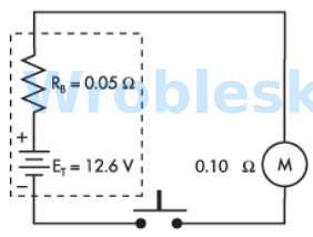
  • Use the diagram to determine the power consumed by the motor when the push buttonis depressed. (Round the FINAL answer to the nearest whole number.)Note: All voltage sources contain internal resistance that is usually ignored incalculations because the resistive value of the load is so much greater than theresistance of the source. This is not always the case. (Rb represents the battery's internalresistance.)Answer:

    Use the diagram to determine the power consumed by the motor when the push button

    is depressed. (Round the FINAL answer to the nearest whole number.)

    Note: All voltage sources contain internal resistance that is usually ignored in

    calculations because the resistive value of the load is so much greater than the

    resistance of the source. This is not always the case. (Rb represents the battery's internal

    resistance.)

    Answer:

    The correct answer is: 144 W

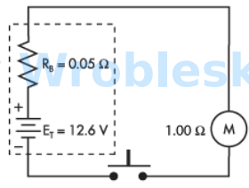
  • Use the diagram to determine the power consumed by the motor when the push buttonis depressed. (Round the FINAL answer to one decimal place.)Note: All voltage sources contain internal resistance that is usually ignored incalculations because the resistive value of the load is so much greater than theresistance of the source. This is not always the case. (Rb represents the battery's internalresistance.)Answer:

    Use the diagram to determine the power consumed by the motor when the push button

    is depressed. (Round the FINAL answer to one decimal place.)

    Note: All voltage sources contain internal resistance that is usually ignored in

    calculations because the resistive value of the load is so much greater than the

    resistance of the source. This is not always the case. (Rb represents the battery's internal

    resistance.)

    Answer:

    The correct answer is: 15.7 W

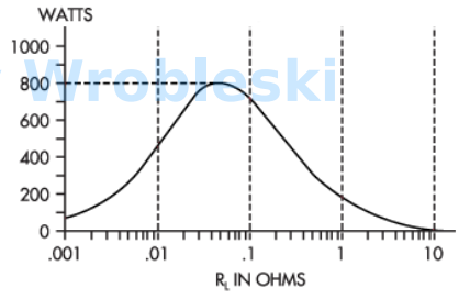
  • What is the value of RL when the wattage is at peak?a.0.01 Ωb.0.25 Ωc.0.05 Ωd.1.00 Ω

    What is the value of RL when the wattage is at peak?

    a.

    0.01 Ω

    b.

    0.25 Ω

    c.

    0.05 Ω

    d.

    1.00 Ω

    The correct answer is: 0.05 Ω

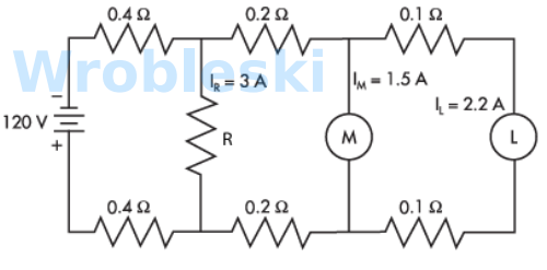
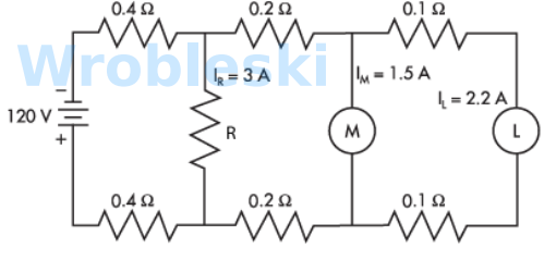
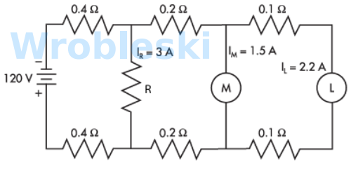
  • Use the diagram to determine the voltage drop across the resistor R. (Round the FINALanswer to two decimal places.)Answer:

    Use the diagram to determine the voltage drop across the resistor R. (Round the FINAL

    answer to two decimal places.)

    Answer:

    The correct answer is: 114.64 V

  • Use the diagram to determine the voltage drop across load M. (Round the FINAL answerto two decimal places.)Answer:

    Use the diagram to determine the voltage drop across load M. (Round the FINAL answer

    to two decimal places.)

    Answer:

    The correct answer is: 113.16 V

  • Use the diagram to determine the voltage drop across load L. (Round the FINAL answerto two decimal places.)Answer:

    Use the diagram to determine the voltage drop across load L. (Round the FINAL answer

    to two decimal places.)

    Answer:

    The correct answer is: 112.72 V