Recovery Systems - Spring grove rockets
advertisement

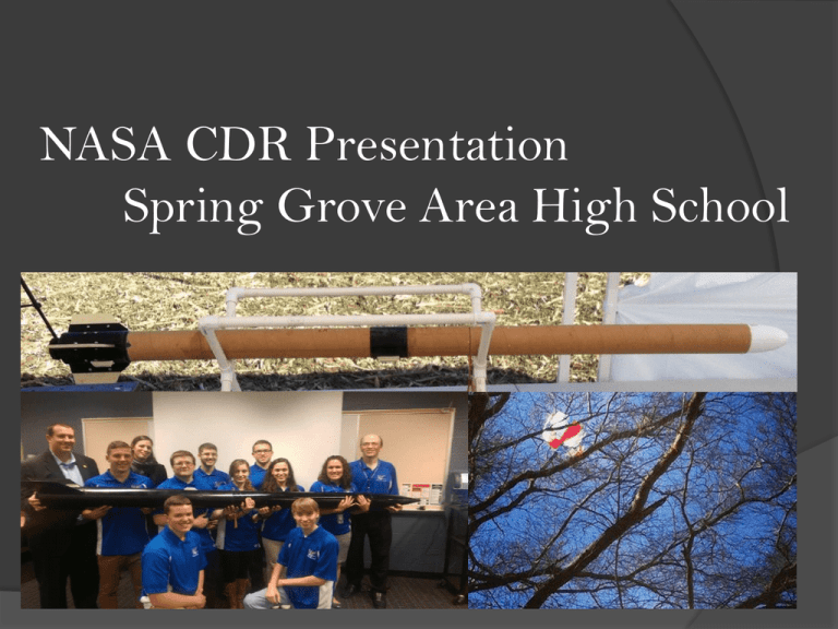
NASA CDR Presentation Spring Grove Area High School 2015 Full-Scale Rocket Length: 114.50 inches Weight: 23.35 pounds Diameter: 4.0 inches Body Tube : Fiberglass Wrapped Phenolic Tubing Center of Pressure: 81.97 inches Center of Gravity: 71.09 inches Static Stability Margin: 2.72 Drag: 1.2 based on nose-cone shape, body material, and fin shape Rocket Continued…… •We will use a 75 mm Motor Retainer that is epoxied onto the ¾” lip of the motor tube that is exposed from the back centering ring. •The fins will be made from 1/8th inch thick G-10 Fiberglass that will allow the rocket to have low drag and also allow the rocket to have a stable stability margin. Payload Will determine the effect of size of single port holes on the measurements taken by Stratologger CF altimeters Variance between measurements can help us potentially find a way to calculate the ideal port hole size Payload (cont.) Four 3D printed bulkheads ½” in thickness Holes for all thread and U-bolts are printed on piece Payload (cont.) Three of the bulkheads will have walls to accommodate altimeters Three altimeters per section One 9V battery in each section will power the three altimeters 9V battery will be secured to the bulkheads Payload (cont.) Battery will be wired to the altimeter in parallel Payload can be activated for hours, in case the rocket would remain on the launch pad for a long period of time Payload (cont.) Two lines of ¼” all thread will run through the entire payload A U-bolt will be attached to each end to connect the payload to the other components of the rocket Entire payload will be approximately 15” in length Fin Brackets The fin brackets will provide a way to easily secure fins to the body of the rocket The fins or the bracket can be replaced if any damage were to occur Fin Brackets (cont.) The fin bracket is two pieces, which will be bolted together The fins are bolted within the fin slots, and the entire piece is then attached to the body tube Fin Brackets (cont.) A single piece of the fin bracket can print overnight: one complete bracket can be made in two days Full scale bracket is two separate parts, due to the size restraints of the 3D printer Plastic Material Material used for 3D printing: polylactic acid plastic Melting temperature between 315 and 338 degrees Fahrenheit Electronics Bay Dual Deployment Two Altimeters with a separate battery for each. They will be wired in series to 9 Volt batteries Final Motor Selection Our final motor selection for the full-scale rocket will be the K-510 Classic motor made by Cesaroni Technologies Incorporated. Impulse of 2,486 Newton*Seconds 75 mm, two grain motor 13.78 inches long. Static Stability Margin Diagram Rocket Data Thrust-to-Weight Ratio- 4.949 Rail Size/Length- 1515 Rail, 120 inches in length Rail Exit Velocity- 53.1 ft/s Center of Pressure- 81.87 in from nose cone Center of Gravity- 71.09 in from nose cone Static Stability Margin- 2.72 Mass Statement There is a 198 ounce mass limit that could be added to the rocket and the rocket still be capable of flying. This number was found to be the limit where the rocket would still be stable by the time it left the launch rail. Recovery Systems The chutes we are using are a Fruity Chutes Standard 24 inch drogue chute and a Iris Ultra 72 inch main parachute. • The 24 inch drogue chute will come out at apogee. A charge in the electronics bay will push out the payload and the chute from the back half of the rocket. • There will be a second charge that goes off two seconds after the first charge to ensure everything was deployed properly. This charge will come from the redundant altimeter. • Recovery Systems The second chute is our 72 inch main parachute, being a Fruity Chutes Iris Ultra with a Coefficent of Drag of 2.2, enough to slow the rocket to a velocity of 17.1 feet per second on impact. • This chute will be deployed at 700 feet by another charge in the electronics bay. This charge will separate the electronics bay and the 72 inch parachute from the front half of the rocket. • This charge will also have a backup delayed at 600 feet to ensure proper deployment. • Recovery Systems Parachute Size- 24” Drogue Harness Length- 15 ft Harness Material- Tubular Nylon Harness Size- 1 inch Terminal Velocity- 52.03 ft/s Size- 72” inch Iris Ultra Main Length- 25 feet Material- Tubular Nylon Size- 1 in Terminal Velocity- 17.1 ft/s Kinetic Energies At Apogee Payload- 59.63 Ft/lbs Back Half- 365.1 Ft/lbs Front Half- 293.2 Ft/lbs At 700 feet / Landing Payload- 9.07 Ft/lbs Electronics Bay- 6.53 Ft/lbs Back Half- 53.65 Ft/lbs Front Half- 42.3 Ft/lbs Drift Calculations With the 24 inch drogue and 72 inch main parachute…. Testing Results The fin bracket held up on flight and was very strong and durable, taking no damage and holding up on both flight and landing The ground ejection test went well and according to plan. The rocket with 3.5 grams of black powder easily ejected the front half of the rocket from the electronics bay. Subscale Data On Flight 1, the rocket achieved a height of 2,075 feet. The rocket was very stable and maintained a nice straight path on flight The rocket with its’ dual deployment payload deployed the payload and drogue chute at apogee correctly and the main at 600 feet. The payload had one altimeter in it to make sure that data could be recorded. That altimeter read 2,071 feet and functioned correctly allowing us with confidence building the full-scale rocket. Subscale cont…. Failure Modes Rocket being too massive for proposed motor To mitigate this we will check the masses of the material compared to the mass on RockSim Construction will be carefully monitored so that every part of the rocket will be strong Failure Modes Looking at the design of our payload conceivable failures are the payload exerting to great of a force on the shock cord and it snapping. To mitigate this failure we will use shock cord tested to hold 2000 pounds of force and a U-Bolt bolted into the top bulkhead of payload. Personnel hazards Some new personnel hazards that have came up during subscale building include: Sawdust going on floor and having the tile be very slick to walk on. Using superglue and having sharp pieces of it go into your hand. To mitigate these risks we will clean up as we work and be more careful when using any type of adhesive Interfaces and Integration Educational Engagement Rocketry Camp: After presentation participation slip 7th and 8th graders build rockets with supervision Other Activities 6th grade and under ○ Able to watch ○ Rocket poem and dance ○ Rocket building snack activity Educational Engagement Rocketry Presentation: We will be holding presentations: ○ February 9th and 10th ○ 7th and 8th grade ○ Survey We will explain the NASA Student Launch rocketry program, as well as our Team America Rocketry Challenge Program. ○ Middle School TARC team PowerPoint: ○ Mission ○ Instructions on building a basic rocket WGAL Preview https://www.youtube.com/watch?v=UHcsiUWZ5U Conclusion We are currently right on target with the suggested timeline. The building and testing of the full-scale rocket is next. ANY QUESTIONS?


