Homework Set 5
advertisement

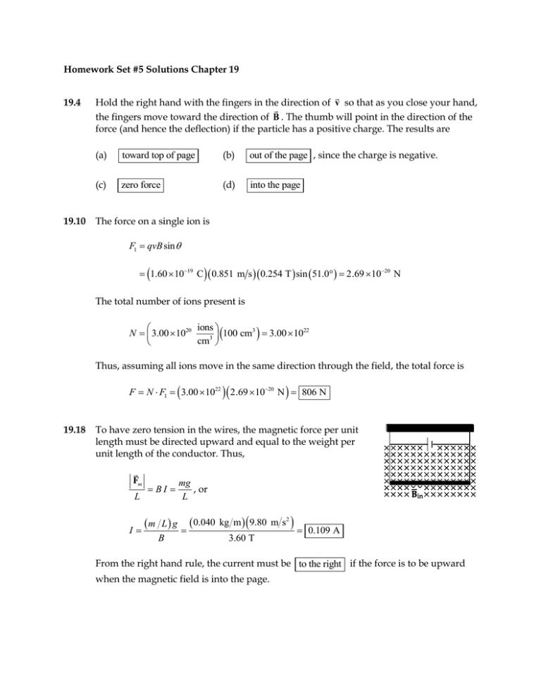
Homework Set #5 Solutions Chapter 19 19.4 19.10 Hold the right hand with the fingers in the direction of v so that as you close your hand, the fingers move toward the direction of B . The thumb will point in the direction of the force (and hence the deflection) if the particle has a positive charge. The results are (a) toward top of page (b) out of the page , since the charge is negative. (c) zero force (d) into the page The force on a single ion is F1 qvB sin 1.60 1019 C 0.851 m s 0.254 T sin 51.0 2.69 1020 N The total number of ions present is ions N 3.00 1020 100 cm3 3.00 1022 3 cm Thus, assuming all ions move in the same direction through the field, the total force is F N F1 3.00 1022 2.69 1020 N 806 N 19.18 To have zero tension in the wires, the magnetic force per unit length must be directed upward and equal to the weight per unit length of the conductor. Thus, Fm L BI mg , or L m L g 0.040 I B kg m 9.80 m s2 3.60 T 0.109 A From the right hand rule, the current must be to the right if the force is to be upward when the magnetic field is into the page. 19.24 The resistance of the loop is R L A 1.70 10 8 m 8.00 m 1.00 104 m2 and the current in the loop is I 1.36 103 V 0.100 V 73.5 A R 1.36 103 The magnetic field exerts torque NBIA sin on the loop, and this is a maximum when sin 1 . Thus, max NBIA 1 0.400 T 73.5 A 2.00 m 118 N m 2 19.26 For the particle to pass through the velocity selector without deflection, it must experience electric and magnetic forces that have equal magnitudes and opposite direction. Thus in this region, Fm Fe , or qvB qE . The speed of the particles entering the deflection chamber is therefore given by v E B . In the deflection chamber, the magnetic force supplies the centripetal acceleration, so mv m E B mE mv 2 , or r qvB qB qB qB 2 r Using the given data, the radius of the path is found to be 2.18 10 1.60 10 26 r 19.33 -19 kg 950 V m C 0.930 T 2 1.50 104 m 0.150 mm From B 0 I 2 r , the required distance is I 4 10 T m A 20 A r 0 2.4 103 m 2.4 mm 2 B 2 1.7 103 T -7 19.39 In order for the system to be in equilibrium, the repulsive magnetic force per unit length on the top wire must equal the weight per unit length of this wire. Thus, F 0 I1 I 2 0.080 N m , and the distance between the wires will be L 2 d d 0 I 1 I 2 2 0.080 N m 4 10 7 T m A 60.0 A 30.0 A 2 0.080 N m 4.5 103 m 4.5 mm 19.42 (a) From R L A , the required length of wire to be used is L R A 5.00 0.500 103 m 1.70 108 m 2 4 57.7 m The total number of turns on the solenoid (that is, the number of times this length of wire will go around a 1.00 cm radius cylinder) is N L 2 r 57.7 m 919 2 1.00 102 m (b) From B 0nI , the number of turns per unit length on the solenoid is n B 4.00 102 T 7.96 103 turns m 0 I 4 10-7 T m A 4.00 A Thus, the required length of the solenoid is N 919 turns 0.115 m 11.5 cm n 7.96 103 turns m 19.49 (a) Since the magnetic field is directed from N to S (that is, from left to right within the artery), positive ions with velocity in the direction of the blood flow experience a magnetic deflection toward electrode A. Negative ions will experience a force deflecting them toward electrode B. This separation of charges creates an electric field directed from A toward B. At equilibrium, the electric force caused by this field must balance the magnetic force, so qvB qE q V d or v V 160 106 V 1.33 m s Bd 0.040 0 T 3.00 103 m (b) The magnetic field is directed from N to S. If the charge carriers are negative moving in the direction of v , the magnetic force is directed toward point B. Negative charges build up at point B, making the potential at A higher than that at B. If the charge carriers are positive moving in the direction of v , the magnetic force is directed toward A, so positive charges build up at A. This also makes the potential at A higher than that at B. Therefore the sign of the potential difference does not depend on the charge of the ions . 19.52 We are given that the field at points on the axis of the disk varies as B k h3 , where k is a constant and h is the distance from the midplane of the disk. At the surface of the disk, B 5.0 103 T and h thickness 1.0 mm 0.50 mm 2 2 Thus, k Bh 3 5.0 103 T 0.50 mm . The distance from the center plane of the disk 3 to the height where B 5.0 105 T is then 1 1 5.0 102 T 0.50 mm 3 3 k 3 3 h 1.0 10 0.50 mm 5.0 mm 5.0 105 T B 1 3 The distance of this position above the surface of the disk is x h thickness 1.0 mm 5.0 mm 4.5 mm 2 2


