Chapter 24 Young and Friedman, 13 th ed. 24.1. Identify: The
advertisement
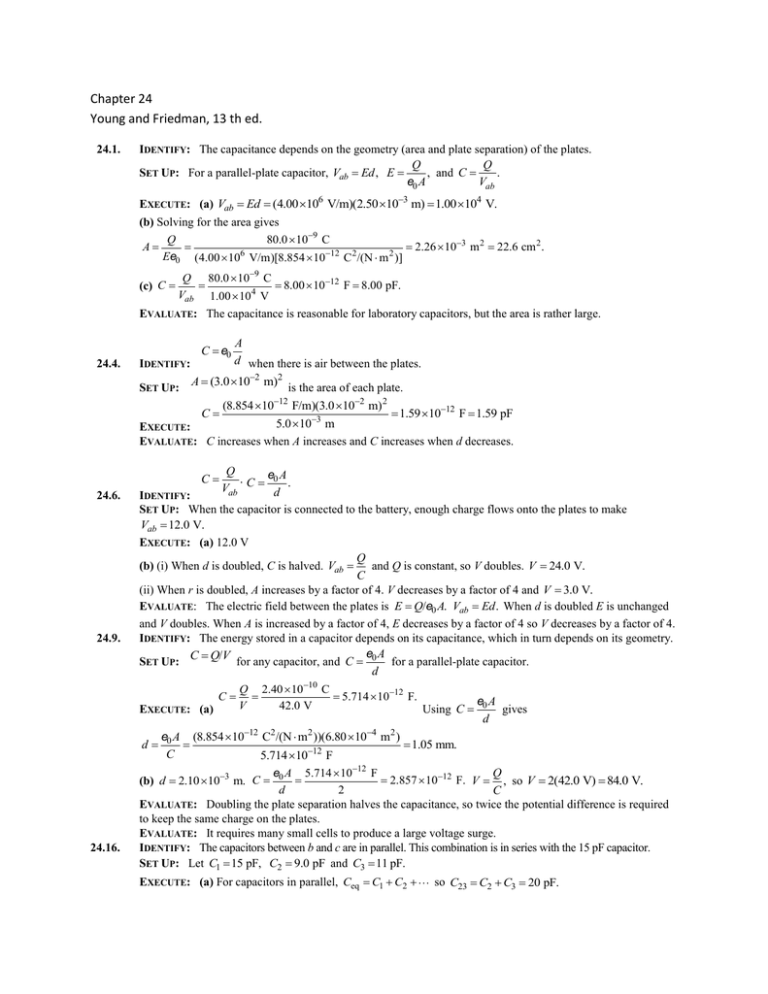
Chapter 24 Young and Friedman, 13 th ed. 24.1. IDENTIFY: The capacitance depends on the geometry (area and plate separation) of the plates. Q Q SET UP: For a parallel-plate capacitor, Vab Ed , E , and C . Vab e0 A EXECUTE: (a) Vab Ed (400 106 V/m)(250 103 m) 100 104 V. (b) Solving for the area gives Q 800 109 C A 226 103 m 2 226 cm 2 . Ee0 (400 106 V/m)[8854 1012 C 2 /(N m 2 )] Q 800 109 C 800 1012 F 800 pF. Vab 100 104 V EVALUATE: The capacitance is reasonable for laboratory capacitors, but the area is rather large. (c) C 24.4. A d IDENTIFY: when there is air between the plates. A (30 102 m)2 SET UP: is the area of each plate. (8854 1012 F/m)(30 102 m) 2 C 159 1012 F 159 pF 50 103 m EXECUTE: EVALUATE: C increases when A increases and C increases when d decreases. C e0 C 24.6. 24.9. Q e0 A . Vab C d . IDENTIFY: SET UP: When the capacitor is connected to the battery, enough charge flows onto the plates to make Vab 120 V. EXECUTE: (a) 12.0 V Q (b) (i) When d is doubled, C is halved. Vab and Q is constant, so V doubles. V 240 V. C (ii) When r is doubled, A increases by a factor of 4. V decreases by a factor of 4 and V 30 V. EVALUATE: The electric field between the plates is E Q/e0 A. Vab Ed . When d is doubled E is unchanged and V doubles. When A is increased by a factor of 4, E decreases by a factor of 4 so V decreases by a factor of 4. IDENTIFY: The energy stored in a capacitor depends on its capacitance, which in turn depends on its geometry. C Q/V for any capacitor, and C e0 A for a parallel-plate capacitor. SET UP: d 10 Q 240 10 C C 5714 1012 F. eA V 42 0 V EXECUTE: (a) Using C 0 gives d d e0 A (8854 1012 C2/(N m2 ))(680 104 m2 ) 105 mm. C 5714 1012 F Q e0 A 5714 1012 F 2857 1012 F. V , so V 2(420 V) 840 V. d 2 C EVALUATE: Doubling the plate separation halves the capacitance, so twice the potential difference is required to keep the same charge on the plates. EVALUATE: It requires many small cells to produce a large voltage surge. IDENTIFY: The capacitors between b and c are in parallel. This combination is in series with the 15 pF capacitor. SET UP: Let C1 15 pF, C2 90 pF and C3 11 pF. (b) d 210 103 m. C 24.16. EXECUTE: (a) For capacitors in parallel, Ceq C1 C2 so C23 C2 C3 20 pF. (b) C1 15 pF and C123 is in series with C23 20 pF. For capacitors in series, C1C23 (15 pF)(20 pF) 86 pF. C1 C23 15 pF 20 pF 1 1 1 Ceq C1 C2 so 1 1 1 C123 C1 C23 24.20. EVALUATE: For capacitors in parallel the equivalent capacitance is larger than any of the individual capacitors. For capacitors in series the equivalent capacitance is smaller than any of the individual capacitors. IDENTIFY: For capacitors in parallel the voltages are the same and the charges add. For capacitors in series, the charges are the same and the voltages add. C Q/V . SET UP: C1 and C2 are in parallel and C3 is in series with the parallel combination of C1 and C2 . EXECUTE: (a) C1 and C2 are in parallel and so have the same potential across them: 6 Q2 400 10 C 1333 V. Therefore, Q1 V1C1 (1333 V)(600 106 F) 800 106 C. Since C2 300 106 F C3 is in series with the parallel combination of C1 and C2 , its charge must be equal to their combined charge: V1 V2 Q3 400 106 C 800 106 C 1200 106 C. (b) The total capacitance is found from Vab Qtot 1200 106 C 374 V. Ctot 321 106 F V3 EVALUATE: 24.25. 1 1 1 1 1 and Ctot 321 F. Ctot C12 C3 900 106 F 500 106 F Q3 1200 106 C 240 V. C3 500 106 F Vab V1 V3. IDENTIFY and SET UP: The energy density is given by Eq. (24.11): u 12 e0 E 2 Use V Ed to solve for E. V 400 V 800 104 V/m. d 500 103 m Then u 12 e0 E 2 12 (8854 1012 C2 /N m2 )(800 104 V/m)2 00283 J/m3. EXECUTE: Calculate E: E EVALUATE: E is smaller than the value in Example 24.8 by about a factor of 6 so u is smaller by about a factor of 62 36. 24.30. IDENTIFY: The two capacitors are in series. 1 1 1 Ceq C1 C2 C Q . U 12 CV 2 . V SET UP: For capacitors in series the voltages add and the charges are the same. 1 1 1 Ceq C1 C2 CC (150 nF)(120 nF) 667 nF. EXECUTE: (a) so Ceq 1 2 C1 C2 150 nF 120 nF Q CV (667 nF)(36 V) 24 106 C 24C (b) Q 24C for each capacitor. U 12 CeqV 2 12 (667 109 F)(36 V) 2 432 J (c) (d) We know C and Q for each capacitor so rewrite U in terms of these quantities. U 12 CV 2 12 C (Q/C )2 Q 2 /2C (24 106 C) 2 (24 106 C) 2 240 J 2(150 10 F) 2(120 109 F) Note that 192 J 240 J 432 J, the total stored energy calculated in part (c). 150 nF: U 9 192 J; 120 nF: U Q 24 106 C Q 24 106 C 16 V; 120 nF: V 20 V 9 C 150 10 F C 120 109 F Note that these two voltages sum to 36 V, the voltage applied across the network. EVALUATE: Since Q is the same, the capacitor with smaller C stores more energy (U Q2/2C ) and has a larger voltage (V Q/C). (e) 150 nF: V 24.31. Q . U 12 CV 2 . V SET UP: For capacitors in parallel, the voltages are the same and the charges add. IDENTIFY: The two capacitors are in parallel. Ceq C1 C2 . C EXECUTE: (a) Ceq C1 C2 35 nF 75 nF 110 nF. Qtot CeqV (110 109 F)(220 V) 242C (b) V 220 V for each capacitor. 35 nF: Q35 C35V (35 109 F)(220 V) 77C; 75 nF: Q75 C75V (75 109 F)(220 V) 165C. Note that Q35 Q75 Qtot . U 1 C V 2 12 (110 109 F)(220 V)2 266 mJ (c) tot 2 eq (d) 35 nF: U 35 12 C35V 2 12 (35 109 F)(220 V) 2 085 mJ; 75 nF: U 75 12 C75V 2 12 (75 109 F)(220 V)2 181 mJ. Since V is the same the capacitor with larger C stores 24.66. more energy. (e) 220 V for each capacitor. EVALUATE: The capacitor with the larger C has the larger Q. IDENTIFY: This situation is analogous to having two capacitors C1 in series, each with separation SET UP: For capacitors in series, 1 (d 2 a). 1 1 1 . Ceq C1 C2 1 1 1 e0 A e A 0 EXECUTE: (a) C 12 C1 12 (d a )/2 d a C1 C1 eA eA d d (b) C 0 0 C0 d a d d a d a (c) As a 0, C C0 . The metal slab has no effect if it is very thin. And as a d , C . V Q/C. V Ey is the potential difference between two points separated by a distance y parallel to a uniform electric field. When the distance is very small, it takes a very large field and hence a large Q on the plates for a given potential difference.

