Likely Problems for APC
advertisement
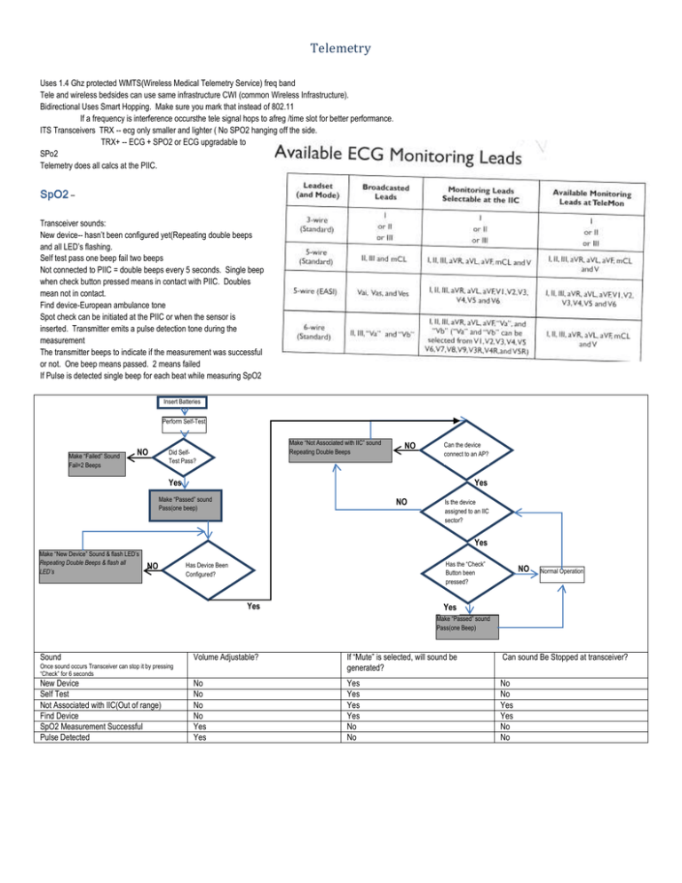
Telemetry Uses 1.4 Ghz protected WMTS(Wireless Medical Telemetry Service) freq band Tele and wireless bedsides can use same infrastructure CWI (common Wireless Infrastructure). Bidirectional Uses Smart Hopping. Make sure you mark that instead of 802.11 If a frequency is interference occursthe tele signal hops to afreg /time slot for better performance. ITS Transceivers TRX -- ecg only smaller and lighter ( No SPO2 hanging off the side. TRX+ -- ECG + SPO2 or ECG upgradable to SPo2 Telemetry does all calcs at the PIIC. SpO2 – Transceiver sounds: New device-- hasn’t been configured yet(Repeating double beeps and all LED’s flashing. Self test pass one beep fail two beeps Not connected to PIIC = double beeps every 5 seconds. Single beep when check button pressed means in contact with PIIC. Doubles mean not in contact. Find device-European ambulance tone Spot check can be initiated at the PIIC or when the sensor is inserted. Transmitter emits a pulse detection tone during the measurement The transmitter beeps to indicate if the measurement was successful or not. One beep means passed. 2 means failed If Pulse is detected single beep for each beat while measuring SpO2 Insert Batteries Perform Self-Test Make “Failed” Sound Fail=2 Beeps NO Make “Not Associated with IIC” sound Repeating Double Beeps Did SelfTest Pass? NO Can the device connect to an AP? Yes Yes Make “Passed” sound Pass(one beep) NO Is the device assigned to an IIC sector? Yes Make “New Device” Sound & flash LED’s Repeating Double Beeps & flash all LED’s NO Has the “Check” Button been pressed? Has Device Been Configured? Yes NO Normal Operation Yes Make “Passed” sound Pass(one Beep) Sound Volume Adjustable? If “Mute” is selected, will sound be generated? Can sound Be Stopped at transceiver? No No No No Yes Yes Yes Yes Yes Yes No No No No Yes Yes No No Once sound occurs Transceiver can stop it by pressing “Check” for 6 seconds New Device Self Test Not Associated with IIC(Out of range) Find Device SpO2 Measurement Successful Pulse Detected Operation: Transceiver Buttons: Remote Alarm Pause/suspend Initiated at transceiver by pressing “transmitter” & Check Buttons at the same time. Lasts for 3 Minutes. Terminated by either pressing both buttons again till the LED turns off or end it at the PIIC. Doesn’t work when Telemon connected Configuration is done in unit settings and is Patient related (must admit the patient) Telemetry Button- Nurse Call alarm and/or recording or No function at all Leadset Type. EASI shows up with light on EASI also Telemetry Button- Nurse Call alarm and/or recording or No function at all Telemetry Button- Nurse Call alarm and/or recording or No function at all SpO2 Mod- Off, Spot Check or Continuous. Check ButtonStatus is check with Audio indicator. Leadset,EASI Mode, Battery Status. 1 beep- IIC association 2 beeps –not associated Broadcast to desired transceiver. If received the transceiver generates “European Ambulance sound. Suppresses Inops if an NIBP is being Made. Enable/Disable pleth wave to the IIC Enable/Disable Pulse Parameter to the IIC Enable/Disable SpO2 alarms at IIC Enable/Disable All Pacer spikes at fixed amplitude Purchase Option=Device location (access Point) shows at the top of the PIIC screen. Will also show the location history if purchased right here Standby: Standby Duration times are infinite to 10 minuts. Clinicians put the device in standby from the PIIC for however long they believe the patient will be out of range. Appr time till resume shows in the standby window. Unit uses the most battery juice when coming out of standby looking for an AP. Action Transceiver in Range Transceiver Out of Range Clinical operator presses “Resume Monitoring at PIIC Monitoring resumes at PIIC Standby remains at PIIC Clinical operator presses Check Button on Trnsceiver Monitoring Resumes at PIIC Standby Remains at PIIC Clinical operator set standby time duration in transceiver Monitoring Resumes at PIIC Standby Remains at PIIC expires Setup which leads to use at IIC NBP at IIC Telemetry Button Telemetry Device Volume: Standby duration Enable Remote suspend Battery Gauge Fixed Pacer Amplitude: Enable SpO2 SpO2 Mode Suppress SpO2 Inops with NBP PIIC response to tele button press. Nurse Call, Record, Both or neither Default volume for transceiver sounds Infinite - 10 min Allows operator from pausing(suspending or resuming alarms at transceiver Displays battery gauge for each assigned transceiver on PIIC Pacer spikes at fixed amplitude Enable/disable measurement of SpO2 Sets transceiver SpO2 mod to off, Spot check or continuous Enable/ disable SpO2 algorithm in transceiver to suppress inops if NIBP measurement is Pleth wave Pulse: SpO2 alarm SpO2 Limits (SpO2)Patient Type: RF auto Shutoff Auto Pair Suspend Duration Troubleshooting: Service tools are Transceiver Sounds IIC system Validation Tool (always run after making changes to system)(You can double click on messages for related help) PIIC status log Wireless Status log==“Wireless Monitoring Loss—Contact Service shows if any of following occur o Duplicate IP Address o Loss of APC o No Master APC o Loss of Remote Antenna o Loss of AP o Local Sync Loss o Remote Sync Loss o Insufficient Spectrum: Only 2.4 GHz The alerts are reported in the Wireless Status Log The system message clears once the log is accessed and the problem no longer exists Categorized by Urgency: o Yellow-Result in Wireles monitoring loss—Call service” o Green –Info Only And Type: Hardware or performance Alerts have a “Flag” Set (alert cond is active Cleared(Clear when device boots up) DB containing alerts and stats can’t be cleared. being made Enable/disable pleth wave from transceiver, and display on PIIC Enable/disable Pulse parameter from transceiver, and display on PIIC Enable/disable SpO2 alarms on the PIIC Default high and low SpO2 alarm limts Default alarm type Adult, Peds or Neo Transceiver will shut down after 10 Min Gives “TRANSMITTER OFF” inop. Automatically pairs a mon and tele when physical connection is established Sets alarm suspend time(1,2 or 3 min) APC web browser interface Transceiver Service tool Device LED’s Likely Problems for the TelePak: Poor ECG quality when used in showere due to water collecting in connector. Should encourage use of the Pouch with protective flap. The transceiver won’t be damaged but the leadset will have to be dried out. Likely Problems for AP: Check for active connection between AP and APC: Go into Philips wizard: and go to status tab If screen is displayed, the AP is communicating with the APC Note that a lot of info is on this screen: IP address Channels Firmware Rev LED status(available for 1.4 core AP. Not for the standard AP) Keep pressing F5(refresh) to see if network and Radio LED’s are OK. Screen doesn’t refresh on its own. Remote antenna Status Dip Switch setting Insufficient spectrum status Power/Sync flashing green-Loss of remote sync unit Flashing Red- Loss of sync unit connected to this AP AP Self-Test Passed but unregistered Radio LED ON=Amber Ntwk LED on-Amber Power/SyncLED on – Amber Other LED on’s indicate AP failure&need to replace FDX(Full Duplex) off= Device is operatin in half duplex: DIP switch 4 set improperly 100M OFF AP operating at 10 Mbps again DIP 4 set improperly & connected to a switch configured for 10Mbps/Half Duplex. Link OFF=Problem with the network connection. Act-Activity Off continuously : indicates no communication to or from the AP over wired link. Likely Problems for APC: Losing it’s configuration Caused by how the “Master” APC manages transferring the configuration files to the “Slave” APCs. If the installation instructions are not followed precisely, the configuration will not be transferred to ehe “Slave” and if the “slave” ever becomes the “Master” the configuration will appear to be “lost”. Always run the AP/APC upgrader Tool to make certain the configuration is transferred properly!!! Remember that the order things are done, does matter Transceiver Tool Connecting to a Transceiver 1. Connect the service cable between the service PC and transceiver. 2. Start the Application. 3. Click on :Connect 4. Insert batteries into the transceiver 5. The tool updates with status information Coverage Assessment Tool: Transceiver can be programmed to use the LED’s on it to report received signal strength and it will start beeping when the signal strength drops below the “Weak signal” limit of -75dBm Any IIT wireless bedside will report the received signal strength in service mode, in the instrument Telemetry Diagnostic screen. Any MRx defibrillator will report the received signal strength in the “Network Settings” screen Note: the access point and the transceiver both broadcast at the same signal strength so the received signal strength reported by the transceiver will accurately reflect the signal strength received by the access point. The body will impact strength(transmitted and received) so it should be worn the way a patient wears it. Use a pouch and adjust so you can see the LED’s. If you hold it, hold close to the body and away from ECG leadset. Your hand will cause a lot of RF Absorption and result in a poor measurement. 2 operating modes; Philips recommends the average. RSSI(Received Signal Strength Indicator) mode. Can be changed by pressing the “Telemetry button”. Average RSSI mode EASI LED is “on” Provides the average RSSI over the last 3 seconds Point RSSI Mode EASI LED is off Samples and reports RSSI every 25 ms Battery on Telepak shows how strong signal is. There is no audio feedback unless there is no signal which is the double beep. All LED’s on = >49dBm good signal Botom 3 on = -50 to -69 dBM Good Signal Bottom 2 on = -70 to -75 dBM Marginal to weak Bottom 1 = <-75 dBm Weak signal No lights = No connection to AP and Double beep. At the bedside monitor, go into service Mode Navigate from Main setup to Instr. Telemetry: MAC Instr. Tele.: MAC address of the IT radio Module RF access Code IP Address: current IP address Server IP: Bootp Server IP address (APC) Subnet Mask: Subnet Mask of wireless network RSSI: Insturement Telemetry Radios RSSI(Value updates whil window is open Connection status: Active or Inactive. Navigate from Menu to Other to Network Settings: Connection: Displays current Connection status(wired, wireless, or inactive) MAC address: MRx MAC address MAC Instr Tele. : Instrument Telemetry radio module MAC address RF Access Code IP address: Current IP address Server IP: IP address of associated Information center Subnet Mask: subnet mask of wired or wirelesss network RSSI Insturment Telemetry Radio’s Received Signal Strength Indicator ( Value updates shile window is open) Wireless Bedsides and Defibrillators Network connectivity Priorities Wired and wireless connections cant be active at the same time When both are available the wired takes priority If the wired is lost, the wireless will kick in within 1 minute Guidelines Turn on device, Check connectivity messages at the device for information If no icons present, check network option is installed properly and enabled Make certain monitor label in device matches what is on the DBS/IIC Connect monitor to wired network and get that working first, them move to wireless link SPo2-Beep when starts and beeps when done No Beep if initiated@ the PIIC. Buttons are on page 25 Sounds Page 19 Sounds from PIIC 21 Tele Setup Page 34 Tele uses most battery life when seeking page 38 All Controls unit Settings Telemetry J is Highest Rev on Monitor N is Highest Rev on PIIC Monitor always alarms Real-time(May hear before you see) Alarms are Patient Related so you must discharge and admit Smart keys are in config mode or smart key ITS compatible with C and above only Nee to know haw many AP’s Length of Cable Toga UTP cable length Sync to POE < 100 Meters or less than 328 Feet Troubleshooting-AP just go into All controls Status Logs Label Assignment All Controls label assignments SPo2 must be turned on—Don’t forget. Smart Hopping with Remote Antennas (same number of devices even with the Remote Antenna Less expensive Device Location each core APand antenna is unique Access Points can Handle up to 18 wireless clients even if you have Remotes. Syck Network Design If the wireless networkneedsmorethan onesync Unit a Synck network design isrequired. In these situations ther is a singleMaster sync uit and one or more to talk to. 4 synces can be daisy chained together or configured in star topology.

