PROJECT REPORT SHEET
advertisement

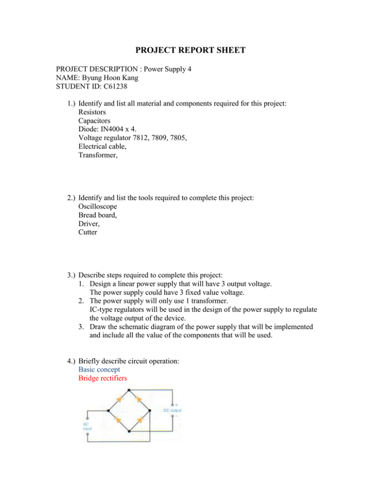
PROJECT REPORT SHEET PROJECT DESCRIPTION : Power Supply 4 NAME: Byung Hoon Kang STUDENT ID: C61238 1.) Identify and list all material and components required for this project: Resistors Capacitors Diode: IN4004 x 4. Voltage regulator 7812, 7809, 7805, Electrical cable, Transformer, 2.) Identify and list the tools required to complete this project: Oscilloscope Bread board, Driver, Cutter 3.) Describe steps required to complete this project: 1. Design a linear power supply that will have 3 output voltage. The power supply could have 3 fixed value voltage. 2. The power supply will only use 1 transformer. IC-type regulators will be used in the design of the power supply to regulate the voltage output of the device. 3. Draw the schematic diagram of the power supply that will be implemented and include all the value of the components that will be used. 4.) Briefly describe circuit operation: Basic concept Bridge rectifiers Schematic diagram. 1. The purpose of 0.5 Ω resistor is to avoid surge current. 2. 3. 4. 5. R = V / I 15V / 30A = 0.5Ω The 7812(+12VDC voltage regulator) produces a 12VDC output as long as 12V to 18V The 7809(+9VDC voltage regulator) produces a 9VDC output as long as 9V to 15V The 7805(+5VDC voltage regulator) produces a 5VDC output as long as 5V to 10V. Capacitor’s function of charge and discharge makes the voltage 5.) Suggested application(s): Power supply 6.) Your observations and comments (if any): No comments. 7.) After completion, test the functionality of the device against requirements. Describe in detail the testing process undertaken and record the data/values Step1. Connect power to transformer. Step2. Measure the value of IC-type regulator. Step3. Observe oscilloscope to find the graph of voltage. 1. Capacitor’s function of charge and discharge. 2. The voltage regulator 7812 cut the input voltage at +12V the output voltage is +12V 3. The voltage regulator 7809 cut the input voltage at +9V the output voltage is +9V 4. The voltage regulator 7805 cut the input voltage at +5V the output voltage is +5V. Diagnose and rectify faults Does the device operate correctly after completion? yes If no, complete sections below. 1.) Describe in detail the action(s) taken to diagnose the fault: No fault 2.) Describe in details the action(s) taken to rectify the fault: No fault 3.) List the faulty component(s) and/or adjustments required to rectify the fault: No fault 4.) Identify the tools required to diagnose the fault: No fault 5.) Identify all material and components required to rectify the fault: No fault 6.) Identify the tools required to rectify the fault: No fault.


