GPS + GPU-E - Tornatech Inc.
advertisement
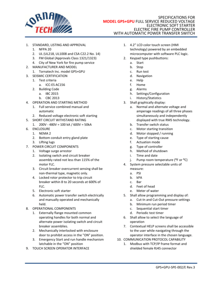
SPECIFICATIONS FOR MODEL GPS+GPU FULL SERVICE REDUCED VOLTAGE ELECTRONIC SOFT STARTER ELECTRIC FIRE PUMP CONTROLLER WITH AUTOMATIC POWER TRANSFER SWITCH 1. 2. 3. 4. 5. 6. 7. 8. 9. STANDARD, LISTING AND APPROVAL 1. NFPA 20 2. UL (UL218, UL1008 and CSA C22.2 No. 14) 3. FM Global (Approvals Class 1321/1323) 4. City of New York for fire pump service MANUFACTURER AND MODEL 1. Tornatech Inc. model GPS+GPU SEISMIC CERTIFICATION 1. Test criteria a. ICC-ES AC156 2. Building Code a. IBC 2015 b. CBC 2013 OPERATION AND STARTING METHOD 1. Full service combined manual and automatic 2. Reduced voltage electronic soft starting SHORT CIRCUIT WITHSTAND RATING 1. 200V - 480V = 100 kA / 600V = 50kA ENCLOSURE 1. NEMA 2 2. Bottom conduit entry gland plate 3. Lifting lugs POWER CIRCUIT COMPONENTS 1. Voltage surge arrestor 2. Isolating switch and circuit breaker assembly rated not less than 115% of the motor FLC. 3. Circuit breaker overcurrent sensing shall be non-thermal type, magnetic only. 4. Locked rotor protector to trip circuit breaker within 8 to 20 seconds at 600% of FLC. 5. Electronic soft starter 6. Automatic power transfer switch electrically and manually operated and mechanically held. OPERATIONAL COMPONENTS 1. Externally flange mounted common operating handles for both normal and alternate power isolating switch and circuit breaker assemblies. 2. Mechanically interlocked with enclosure door to prohibit access in the "ON" position. 3. Emergency Start and run handle mechanism latchable in the “ON” position TOUCH SCREEN OPERATOR INTERFACE 1. 4.2” LCD color touch screen (HMI technology) powered by an embedded microcomputer with software PLC logic. 2. Keypad type pushbuttons: a. Start b. Stop c. Run test d. Navigation e. Help f. Home g. Alarms h. Settings/Configuration i. History/Statistics 3. Shall graphically display: a. Normal and alternate voltage and amperage readings of all three phases simultaneously and independently displayed with true RMS technology. b. Transfer switch status c. Motor starting transition d. Motor stopped / running e. Type of starting cause f. Actuation mode g. Type of controller h. Method of shutdown i. Time and date j. Pump room temperature (⁰F or ⁰C) 4. System pressure selectable units of measure: a. PSI b. kPA c. Bar d. Feet of head e. Meter of water 5. Shall allow programming and display of: a. Cut-In and Cut-Out pressure settings b. Minimum run period timer c. Sequential start timer d. Periodic test timer 6. Shall allow to select the language of operation 7. Contextual HELP screens shall be accessible to the user while navigating through the operator interface in the chosen language. 10. COMMUNICATION PROTOCOL CAPABILITY 1. Modbus with TCP/IP frame format and shielded female RJ45 connector GPS+GPU-SPE-002/E Rev.3 SPECIFICATIONS FOR MODEL GPS+GPU FULL SERVICE REDUCED VOLTAGE ELECTRONIC SOFT STARTER ELECTRIC FIRE PUMP CONTROLLER WITH AUTOMATIC POWER TRANSFER SWITCH 11. STATE AND ALARM VISUAL INDICATORS 1. Shall visually indicate and differentiate the criticalness by color: a. Normal and alternate power phase reversal b. Normal and alternate power/phase loss c. Locked rotor on normal power d. Locked rotor on alternate power e. Fail to start f. Service required g. Undercurrent h. Overcurrent i. Under voltage j. Overvoltage k. Phase unbalance l. Low water level m. Low system (discharge) pressure n. Periodic test cut-in not reached o. Run test solenoid valve check p. Faulty pressure transducer q. Pump on demand r. Over pressure s. Under pressure t. Alternate power isolating switch and circuit breaker open u. Low pump room temperature 12. PRESSURE AND EVENT RECORDING 1. Shall be capable of logging pressure data and operational events with time and date stamp. 2. Shall be able to display the last 500 operational events and display the pressure data in text and/or graphic form. 3. Data shall be retrievable and downloadable to a flash memory disk via the USB port accessible to the user without having to open the controller door. a. Last service statistics (1) Powered since (2) On time (3) Motor last run (4) Motor run time (5) Motor start count (6) Minimum, maximum, average system pressure (7) Minimum, maximum, average pump room temperature (8) Generator last run (9) Generator run time (10) Transfer switch transfer count All time statistics (1) First power up (2) First start up (3) On time c. Power statistics (1) Voltage between phases with date stamp (2) Amperage between phases with date stamp WETTED PARTS 1. Shall be supplied with a pressure transducer and run test solenoid valve assembly rated for 500psi working pressure (calibrated at 0-300psi) and be externally mounted with a protective cover. 2. Pressure sensing line connection to shall be ½” FNPT. 3. Provision for a redundant pressure transducer shall be provided. SERVICE/FLOW TESTING CAPABILITIES 1. Shall have capability of scheduling maintenance reminders. 2. Shall have capability of inputting pump flow test data, generate and display the pump curve and store this information in memory for the lifetime of the controller. CONNECTION FOR EXTERNAL DEVICES 1. Manual remote start device 2. Automatic remote start device 3. Deluge valve start 4. Generator start signal SPDT DRY CONTACTS FOR REMOTE INDICATION OF ALARM CONDITIONS (8A – 250VAC) 1. Power or phase failure and/or circuit breaker in open position 2. Phase reversal 3. Pump run 4. Common pump room alarm (field reassignable) 5. Common motor trouble (field re-assignable) 6. Alternate power isolating switch in the OFF position 7. Transfer switch in the normal position 8. Transfer switch in the alternate position 9. Field programmable AUDIBLE ALARM 1. 4” alarm bell rated for 85dB at 10ft (3m) b. 13. 14. 15. 16. 17. GPS+GPU-SPE-002/E Rev.3
