proposal_final - Engineering Department
advertisement
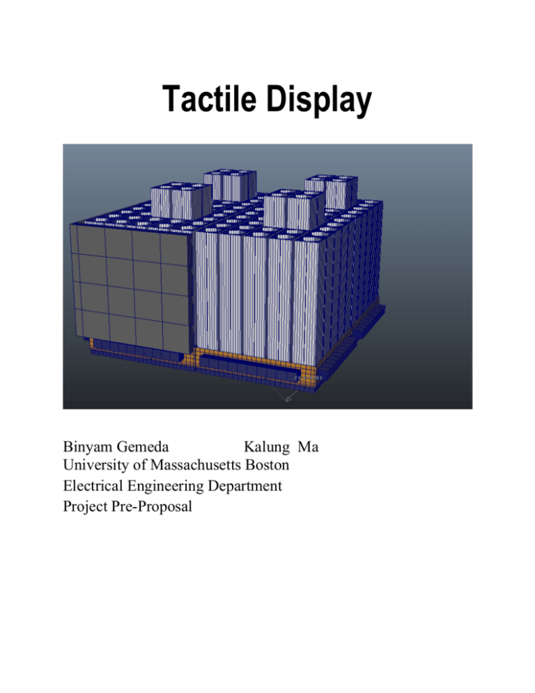
Tactile Display Binyam Gemeda Kalung Ma University of Massachusetts Boston Electrical Engineering Department Project Pre-Proposal Abstract A static tactile display design and implementation is presented in this report. The tactile display will have 360 by 360 mm dimension and holds 10x10 PLA filaments. The filament’s linear motion is controlled by NMB 25-stepper motor. The motors are controlled and driven by Atmega32 and stepper motor driver A4498/SP. The hex file to program the Atmega IC is written in Atmel Studio6. Xeltek SuperPro M universal device programmer will implement the program. The body of the tactile display is thermoplastic polymer such as PLA or ABS that is used for the 3D printer. The display will be equipped with audio output to provide more information for the user. Table of Contents 1. Introduction ............................................................................................................................. 1 2. Background .............................................................................................................................. 1 2.1 Electrical Tactile ................................................................................................................. 1 2.2 Vibro-Mechanical Tactile ..................................................................................................... 2 2.2.1 Electro-Mechanical System ............................................................................................ 2 2.2.2 Pneumatic Tactile System .............................................................................................. 3 2.3 Static Low Frequency Tactile Displays ............................................................................... 3 3. Goals ....................................................................................................................................... 5 3.1. Portability ............................................................................................................................. 5 3.2. Power Efficiency .................................................................................................................... 5 3.3. Display Dimension ................................................................................................................. 5 4. Design ..................................................................................................................................... 5 4.1. Threaded Shaft and Micro Stepper Motor .................................................................................. 5 4.1.1. Threaded Shaft and Micro Stepper Motor ............................................................................... 6 4.2 Second Alternative Approach of Micro Stepper Motor ............................................................. 6 4.3 Filament ............................................................................................................................. 7 4.4 Sound Output ...................................................................................................................... 8 4.5 Touch Input ........................................................................................................................ 9 4.6 Application Software ..........................................................................................................11 5. Work Flow .........................................................................................................................11 6. Engineering Standards for Tactile displays ..................................................................................14 6.1. Guidance on Tactile and Haptic Interaction ..............................................................................15 7. Impacts ...................................................................................................................................17 7.1. Societal Concern ...................................................................................................................17 7.2. Ethical Concern ....................................................................................................................17 7.3. Environmental Concern .........................................................................................................17 7.4. Safety Concern .....................................................................................................................17 8. Team ......................................................................................................................................17 8.1. Team Member Responsibilities ...............................................................................................17 8.2. Team Organization ................................................................................................................18 8.3. Milestones ............................................................................................................................19 8.4. Budget .................................................................................................................................20 Bibliography ..............................................................................................................................21 1. Introduction Any device, which senses information such as shape, texture, softness, temperature, vibration or shear and normal forces, by physical contact or touch, can be termed a tactile sensor [1]. Since the early 1970 several different types of tactile devices are introduced in an effort to minimize power requirements and weight while simultaneously maximizing the stimulus effect [3]. However, Currently Tactile displays are poorly developed. According to Pasquero and Hayward [2], Poor usability is the main reason for very slow development of tactile displays as currently available displays are cumbersome, bulky and very expensive. On the other hand unlike sight and sound, sense of touch is not localized and Difficult to imitate [4]. This may also be a contributing factor for the slow growth of tactile displays. Despite slow growth, tactile device can be used in teleportation and tele-presence, sensory substitution, 3D surface generation, Braille system and games [6]. To help visually impaired persons in a society developing a better social cycle, integrated into community and community activities, there are many technologies help them achieve these thought access to visual text and graphics. This technology has auditory and tactile feedback instead of vision. Auditory feedback is a voice screen reader to transfer information to speech, such as illustration and diagrams. And the tactile feedback can demonstrate the spatial information. Tesla Touch is a successful case of a touch sensitive screen with haptic feedback [10]. 2. Background Tactile displays can generally be categorized as Electrical and Vibro-Mechanical. Other less know tactile display technologies such as Static Low Frequency and Electro-Active Polymer are also available [3]. 2.1 Electrical Tactile Electrical tactile system provides tactile stimulation by inducing electrical current through the skin in a process known as electro-cutaneous stimulation [3]. “The electric field generated then excites the neighboring afferent nerve fibers responsible for normal mechanical touch sensations” McGrath, B., et al (2008). In this type of tactile display there is no mechanical part that moves. As the result of this the electrical tactile displays are slimmer and light weighted than mechanical tactile displays. 1 Fig 1. Extensor Electrical Tactile Stimulation System. (McGrath, B., et al (2008)). 2.2 Vibro-Mechanical Tactile Vibro-Mechanical stimulation activates different types of mechanoreceptors in the skin [2].The response of these receptors are largely dependent up on the frequency, amplitude, duration and the total area of stimulation [2].The optimal frequency of human mechanoreceptors found to be around 150 to 300 Hz [2]. 2.2.1 Electro-Mechanical System Vibro-Mechanical tactile can be categorized in to electro-mechanical and Pneumatic system. Linear actuator and Rotary Inertial tactile system are electro-mechanical system [3]. The rotary inertia types of tactile devices often found in pager motors of cell phones [3]. Linear actuators are coil based actuators that incorporate contactors that oscillate perpendicularly when electric signals are applied [3]. This type of tactile devices designed with primary resonance in the 200 to 300 Hz range, that peak sensitivity of the Pancinian corpuscles of the skin [3]. Fig 2 shows C2 Tactor from Engineering Acoustic that deploys linear actuators. Fig 2. C2 Tactor of Engineering Acoustic (McGrath, B., et al (2008)). 2 2.2.2 Pneumatic Tactile System Pneumatic tactile devices use airflow to create vibration. “Oscillatory compressed air signals are typically generated by sub-miniature solenoid valves connected to either a compressor or pressurized air tank. An example is the Steadfast Technologies P2 tactor. The P2 tactor uses a pressure of approximately 40PSI and a flow of 1 L/min” (McGrath, B., et al (2008)). 2.3 Static Low Frequency Tactile Displays Pin-Based tactile displays, Hydraulic tactile and Piezo-Electric tactile devised are all categorized under Static Low Frequency Tactile displays. Pin based tactile displays are composed of an array of metallic pin arranged in a surface in square or hexagonal manner. The metallic pin forms different patterns to transfer information. Optacon is well known Pin-based tactile display [3]. Fig 3. Optacon tactile display for the visually impaired (courtesy of http://www.dlfdata.org.uk). University of Stuttgart, Visualization and Interactive System Institute develop Pin-base tactile web browsing system for blind people [5]. Fig 4 Metec Display Tactile web browser (Rotard, Martin, Christiane Taras, and Thomas Ertl (2008)). 3 The Hydraulic tactile display is very similar to the Pneumatic device except that it uses fluid instead of air. Electro-Active Polymers and Micro-Electro-Mechanical systems consider as technologies that are under development for future use. Electro-Active polymers contract and expand in the presence of eclectic current [3]. Micro-Electro-Mechanical System (MEMS) deploys sensors, actuators and mechanical devices on a common silicon substrate [3]. One type of hydraulic tactile display is shown in Fig 5. The device is developed by Hull University researchers [6]. Fig 5. 5x5 tactile display based on electro rheological fluid [6]. Researchers at University of Carnegie Mellon, Micro-electromechanical System Laboratory developed a tactile interface chip based on MEMS technology [6]. The MEMS chip contains 24 actuators of different size on a surface of 1cm^2 [6]. Fig 6. Micro-Electro-Mechanical System (MEMS) [6]. The motivation for this project is to develop cheap and portable static tactile display by using micro stepper motors. By only moving 10 stepper motors at a time and locking the filament at a given position, the project also aim to significantly reduce the power needed to operate the display. By developing portable and affordable tactile display, individuals who have visual or/and hearing disability will benefit immensely. 4 3. Goals 3.1. Portability The usability of tactile device can be significantly improved by making the device portable and cheap. In this project, the standard linear actuator motors for static tactile display will not be used as these motors are very expensive and drive the coast significantly higher. Mini stepper motors are cheaper alternative. By constraining the circular motion in the X and Y axis of the shaft of the micro-stepper motor, a linear motion in the y axis can be achieved. Since micro stepper motors are very small in the range of 6mm to 15mm in diameter and 4mm to 10mm high, employing these types of motors can significantly reduce the bulkiness of the tactile display. 3.2. Power Efficiency The power consumption of micro stepper motors is very small. A typical micro stepper motor with 30 ohm internal resistance requires 3 to 5V and about 0.1A current. To move 10 micro stepper motor at a given time, 1 A current is needed. 3.3. Display Dimension The Tactile display will have 10x10 arranged 100 filaments. The filaments are separated by 1mm.Each filament moves 0 to 75mm.The size of the display is expected to be 350mm by 350mm.Some modification may be applied depending on the final design of the display. 4. Design 4.1. Threaded Shaft and Micro Stepper Motor Advancement in motor technology provides several alternatives to create linear motion. Motors that provide accuracy in micrometers ranges are available in the market. The price tag per motor however is very high. Single piezo linear actuator can cost more than hundred dollars. Since several motors are needed, expensive actuators are not considered. Micro stepper motor such as Sanyo or NMA 2phase bipolar stepper motor is selected. The motor provides 18-degree step angle, which is 20 steps per 360 degrees.10 motors, cost about 20 dollars, as shown in Figure 7. The motor comes with threaded shaft and small lock for linear motion. The housing of the tactile display will be printed using 3D printer. The material of choice is PLA. If the motor heats too much, ABS may be used. 5 Fig 7. 18-Degree Step Angle in Micro Stepper Motor 4.1.1. Threaded Shaft and Micro Stepper Motor NMB 2 phase 4 wires stepper motor is considered for this design. The stepper motor needs 3 to 5 v. The stepper motors will then be coupled with threaded shaft on the blocks with PLA coupler design and printed by the team. Fig 11. NMB 2phase bipolar stepper motor. 4.2 Second Alternative Approach of Micro Stepper Motor The team also comes up with a second alternative approach to the project. In this approach 4 6 NEMA 14 stepper motors are used. The housing that holds the single stepper motor that rotates the threaded shafts moves in the XYZ direction by three NEMA 17 stepper motors which are shown in Figure 12. To accomplish this, six linear ball bearings and shafts will be used. Timing gear and Pinion pulleys are also needed. This approach requires a much more precise movement of motors in the XYZ direction. The advantage of this system is that it only uses four motors. However, the display would be expected to be bulkier and heavier and slower in this design approach. Fig 12. NEMA 17 stepper motor. 4.3 Filament To gain higher filament altitude, the group also considered a different design approach. Filament that have dimension of 14.5 x 14.5 mm and 72.5mm height is mounted on 6.32mm threaded shaft. 25 shafts are mounted on 70x70 mm PLA bock as shown in Fig 8. Fig 8. 5x5 filament assembly on PLA block. 7 Four of such blocks will be assembled to form the 10x10 filament assembly as shown in Fig 9 and 10. Each filament's threaded shaft is driven by single stepper motor. Fig 9. 10x10 Filament Assembly. Fig 10. 10x10 filament top view. 4.4 Sound Output Each filament will be equipped with small button that will inform the microcontroller its XYlocation on the display. The filament location will be used to give more information by providing sound output. APR 9600/APR33A3 chip or other similar sound record and playback modules such as ISD 1932 will be used to achieve this goal. 8 Fig 13. ISD 1932 sound record and playback module from spark fun. Again, according to datasheet of ISD1932, the operating voltage (Vcc) is between 2.4V to 5.5V, as shown in Figure 14. ISD1932 can provide 5.5V to each button when it is being used. ’ Fig 14. Operating Conditions of ISD 1932. 4.5 Touch Input To create the touch input for the sound output, 100 buttons will be installed on the top of each filament. What we have in the Tactile Display is 100 buttons and 10 signal lines, which contains 10 inputs and 10 outputs. The basic set-up is in a grid pattern where the 10 input lines come down as 10 columns (pin 1 to pin 10), and the 10 output lines come across as rows (pin 11 to pin 20). Each column connects a 1k resistor. Every row, which can be regarded as an output, connects to the Atmega32. The touch button serve as an input to the sound record and play back module to inform the users what kind of things in the picture you are touching. It is shown in figure 15. 9 Figure 15 – Draft of Schematic Diagram of Touch Sensor Again, each button is a momentary on button, which means each button is normally open and is in an open circuit. When a button is hit, it will make a connection between the button input and output, and become a complete circuit. Otherwise, there is no connection. To control the buttons, 5.5V can be supplied to the column and let the rows connection go to multiplier and ISD 1932 sound record playback module. Choosing a correct resistor can protect the buttons better. Since only one button in a column should be pressed at once, the size of resistor can be calculated by using Ohm’s Law (V=I*R). According to the data sheet of button, the switching current of absolute maximum is 50mA. It means the button allows 50mA current in maximum to flow. Also, the switching voltage maximum is 42V DC, as shown in Figure 16. Figure 16 - The Maximum Value of Switching Voltage and Current of Button Therefore, when it is assumed to be max operating current and the voltage drop, 110Ω of resistor can be allowing for the max current with 5.5V input. 10 4.6 Application Software Student from computer science department will develop the application software. If no student is available to participate in this project, the help of an application developer will be considered. For the application software, an image initially is converted in to depth map using software such as Photoshop or Crazy Map. The images can be directly taken by camera that has capability to take depth map. The pixels then divided in to 10x10 regions. The value of bite map of the depth map is averaged for each square area. The value of the depth map of each pixel can be read by Matlab image processing algorithm. A total of 100 depth map values that range from 0 to 1 is generated. These values are sent to the micro-controller through standard communication protocol. The micro-controller then uses the values to determine how many steps should each stepper motors go. 5. Work Flow For the first part of this project, it is 3D design, printing and assembling of the tactile display components. Once the 3D printed filaments and threaded shafts are mounted on PLA block, the blocks will be fitted in to stepper motor assembly blocks that hold NMB stepper motors with PLA housing. Each functional unite blocks is fitted with buttons that will be used as input for the sound record and play back module. Functional blocks then assembled to form the 10x10 tactile displays. Atemega32, H-Bridge or stepper motor driver module A4988/SP, Mux/DeMux (74HC4051) and an array of transistor (2N7000) will be deployed to control stepper motors on functional blocks. Another Atmega32, an array of tactile switch off momentary on single pole single throw input button and ISD 1932 modules will be used to create button input and sound output features of the tactile display. Fig 16 Stepper motor driver A4988/SP, Atmega328P IC, SPST button ,2N7000 MOSFET, Xeltek Superpro M. Studio6 of Atmel will be used to program the Atmega IC chips. Once the hex files are generated, universal devise programmer Xeltek SuperProM will be used to implement the hex files on the IC chips. 11 Fig 17. A microcontroller, decoder and two motors configuration (illustration only not actual design). Fig 17. Atmel Studio6 AVR programming software. Fig 18. Printrbot Simple Metal 3D printer. 12 Fig 17. Flow chart of Tactile display. Fig 18.Flow diagram of Tactile display. 13 Fig 19. Work flow diagram for the application software. 6. Engineering Standards for Tactile displays As tactile displays are becoming more and more versatile, engineering standards can ensure that systems are designed with sufficient concerns for ergonomic and interoperability [7]. Ergonomic standards provide better consistency and interoperability but also improve effectiveness and avoid errors, improve performance and enhance the comfort and wellbeing of users [7]. Tactile device usability and applicability’s are dependent up on multitude of variables. Some of the most common performance measurement factors and variables according to McGrath, B., et al (2008) are: I. Magnitude – Peak-to-peak amplitude of the mechanical/electrical output signal; II. Frequency – Number of cycles per second at which the tactor stimulus operates; III. Waveform – Descriptive shape of stimulus pattern (e.g., sine wave, square wave, saw tooth); IV. Pattern – Set of ordered, repeating stimulations; V. Duration – Time interval the tactor is active; VI. Location – Position on the body where the tactor stimulates the tissue; VII. Contactor Size – Surface area of the electrode or displacement (moving) portion of the tactor; and 14 VIII. Interstimulus Interval – Time interval between the conclusion of one tactile stimulation and the beginning of the next. For tactile and haptic devices new set of standards are developed by International Organization for Standards (ISO). “ both ISO and CEN standards, provide ergonomic requirements and recommendations for haptic and tactile hardware and software interactions, including guidance related to the design and evaluation of hardware, software, and combinations of hardware and software interactions” Van Erp, Jan BF, et al(2010) as shown below. 6.1. Guidance on Tactile and Haptic Interaction Applicability considerations for haptic interactions, including: limits to effectiveness, workload considerations (efficiency), user acceptance considerations (satisfaction), workload considerations (efficiency), user acceptance considerations (satisfaction), workload considerations (efficiency), user acceptance considerations (satisfaction),and security and privacy [9]. Tactile/haptic inputs, outputs, and/or combinations, including: unimodal and multimodal use of haptic interactions, intentional individualization, and unintentional user perceptions. Attributes of tactile/haptic encoding of information, including: using properties of objects, using perceptual attributes, and combining attributes[9]. Content-specific encoding (what to encode), including: encoding and using textual data, encoding and using graphical data, encoding subjective data, and encoding and using controls [9]. Layout of tactile/haptic objects, including: resolution, separation, and consistency [9]. Interaction, including: interaction tasks (such as navigation, selection, and manipulation) and interaction techniques (such as moving objects, possessing objects, and gesturing). Guidance for specific haptic interactions related to reading tactile alphabets and notations suitable for blind or deafblind people are handled byUnicode and other national standard [9]. ISO 9241 and TC159/SC4 provides detail guideline for Tactile/haptic interface [8].A general guideline is also provided by . Carter, Jim, and David Fourney(2005) as shown below. "Interaction should be natural, efficient, and appropriate for target users, domains, and task goals." [16] [8] 15 The system should enable users to interact with and control their movement throughout a virtual environment in a natural, streamlined fashion [16] [8]. The system should provide sufficient movement controls to support all aspects of the task. [16] [8]. Where multimodal output is used, information presented in each modality should be readily understood, unambiguous, and necessary to complete the task. [16] [8]. Where the task allows, haptic output should be seamlessly integrated into the user’s task. [16] [8]. The system should avoid discord between the user’s task and the haptic display. [16] [8]. The system should provide consistent, accurate haptic interaction.[16] [8]. The system should provide intuitive haptic interaction. [16] [8]. The system should provide intuitive haptic interaction. [16] [8]. precise joint rotations The system should avoid requiring minute, precise joint rotations, particularly at distal segments. [9] [8]. . The system should avoid causing user fatigue. [16] [8]. b. The system should avoid requiring static positions at or near the end range of motion to minimize kinesthetic interaction fatigue. [9] [8]. c. The system should ensure user comfort over extended periods of time. [7] The system should use very high spatial resolutions to increase haptic device ease of use. [16] [8]. The system should encode haptic information using combinations of strength, speed, high-resolution force, and position that are effectively presented. [16] The system should effectively use haptic feedback in areas where other senses are unusable. [16] [8]. NOTE: Haptics is rarely used for spatial discrimination by itself (except in dark environments). [13] [8]. While the guidelines in all other subsections (other than 3.1.2) relate to both the unimodal and the multi-modal use of tactile / haptic interactions, there is additional guidance that applies specifically to multi-modal use [8]. According to Popescu et. al., "multisensory feedback is not just the sum of visual, auditory and somatic feedback, since there is redundancy and transposition in the human sensorial process.” [13] [8]. The system should use multimedia information when presenting complex haptic objects [8]. NOTE Users may not understand complex objects when only presented haptic information. [7] [8]. The system may enhance haptic tasks by using other senses and vibratory cues. [16] [8]. 16 The system may make use of tactile stimuli to convey additional information, beyond that presented via other modalities. [9] [8]. EXAMPLE A user performing a visual spatial attention task uses tactile information to communicate warnings. [9] [8].However, care must be taken to use the device for the intended purpose. Inappropriate use may damage the device or can cause injuries. 7. Impacts 7.1. Societal Concern We believe that the tactile display will have a positive impact on the society by providing more accommodation and better way of communication to the visually impaired group of the society. The business community will also be benefited as the display provides efficient way to communicate with the visually impaired. By providing more accommodation to the visually impaired, the challenge that this group of the society face can be reduced and their life quality can be improved. 7.2. Ethical Concern We could not be able to anticipate how and when the tactile display can be used in a manner that is against human moral codes, norms and values. However, care must be taken to use the device for the intended purpose only. Inappropriate use may damage the device or can cause injuries. 7.3. Environmental Concern All the material involved or used in this projects are not toxic and does not have any negative impact on the environment and the devise intended users. The thermoplastics used (PLA) in this project is safe and biodegradable. 7.4. Safety Concern The tactile display can be little bit heavier, so appropriate measures should be taken during transport or use of the device. Just like any other electrical device, precautions must be followed for proper and intended use. 8. Team Project adviser: Prof Ping Chen Team Members : Binyam Gemeda Kalung Ma 8.1. Team Member Responsibilities Binyam Gemeda: 3D designing of Tactile Display, 3D printing Kalung Ma : Stepper Motor Selections, Interfacing with 3D printed parts Team Members (both): Stepper motor controlling and testing, Atmel Studio 6 coding, Device implementation and testing, Find solution for the application software 17 8.2. Team Organization The team was formed in October 22 of 2015 and began having weekly group meeting. Group meeting is held on every single Monday and Wednesday at 1 pm in Library. 8 floor of Healey Library is a perfect place for group discussion. Students are allowed to stay together and discuss. The weekly meeting and Monthly timeline are shown in Table 1, Table 2 and Figure 20. Table 1 – Weekly Schedule of Meeting Date Description 10/26/2015 Discuss the idea of Tactile Display 10/28/2015 Discuss the criteria, difficulties and functionalities of the project design and set up a group meeting schedule 11/2/2015 Discuss work distribution, do research and start doing pre-proposal 11/4/2015 Discuss the managing time, budget and resources 11/9/2015 Discuss the impacts of societal, ethical, risk, and safety 11/11/2015 Review the comments from Prof. Cuckov and revise the pre-proposal 11/16/2015 Review the pre-proposal 11/18/2015 Discuss and review the pre-proposal from customer interactions and work on final team project proposal 11/23/2015 Discuss regulations such as copyright, liability and standards 11/25/2015 Review the comments from Advisor and revise the final proposal 11/30/2015 Review the comments from Advisor and revise the final proposal 12/2/2015 Finish up the preliminary design and final proposal 12/7/2015 Discuss the final report and prepare the final project presentation 12/9/2015 Discuss the final report and prepare the final project presentation September October November December Table 2 – Monthly Timeline Focus on project ideas and project bids Focus on project synopses Focus on the feasibility study, pre-proposal, review comments from Prof. Cuckov, Advisor and Customers. Proposal due: November 15th, 2015 Discuss the final proposal and presentation 18 January February March April May Start the construction part and work subsystems Focus on construction part and review the problems and difficulties Programming of application software Programming of application software Focus on combining all parts of the project design and solve the problem if the design does not work Focus on final report and presentation Fig 20.Chronology of Gantt chart. 8.3. Milestones 1. Complete 3D Design and Print Complete the 3d designing and printing would be the first milestones for this project. 19 2. Interfacing and Single Filament Block Testing Motor and 3D part interfacing and testing would be conducted at this stage. By using simple stepper motor coding the functionality of single filament unites will be tested. 3. Atmel Studio 6 coding and Devise Implementation Stepper motor control and programming will be performed at this stage. Once the code developed and tested for its functionality, devise implementation will be performed. 4. Touch sensor and Sound record/playback module integration The filaments will be mounted with touch sensor and pre-recorded sound will be play back. The sound will identify what is touch or the location or any information associated with the location of the filament. 5. Exploration for Application Software Application software is needed to transfer information from a PC to the Tactile Display. All possible options will be considered at this stage. 8.4. Budget Parts Atmega32 Atmega16/MUX/DMUX PLA/ABS MOTORS H-bridge/driver ISD 1932 Button Total Quantity 2 16/4 2kg 150 10 1 100 $ 789.14 Price 3.98/each 4.98/each 30/kg 4.00/each 4.35/12.45 each 20 0.32/ each The cost for power supply and management is under review. Once that is completed, it will be included in the total cost analysis. 20 Bibliography [1] Tiwana, Mohsin I., Stephen J. Redmond, and Nigel H. Lovell. "A review of tactile sensing technologies with applications in biomedical engineering."Sensors and Actuators A: physical 179 (2012): 17-31. [2] Jones, Lynette A., and Nadine B. Sarter. "Tactile displays: Guidance for their design and application." Human Factors: The Journal of the Human Factors and Ergonomics Society 50.1 (2008): 90-111. [3] McGrath, B., et al. "–TACTILE ACTUATOR TECHNOLOGY." Tactile Displays for orientation, navigation and communication in air, sea and land environments (2008): 4. [4] Lee, Mark H., and Howard R. Nicholls. "Review Article Tactile sensing for mechatronics—a state of the art survey." Mechatronics 9.1 (1999): 1-31. [5] Rotard, Martin, Christiane Taras, and Thomas Ertl. "Tactile web browsing for blind people." Multimedia Tools and Applications 37.1 (2008): 53-69. [6] Benali-Khoudja, Mohamed, et al. "Tactile interfaces: a state-of-the-art survey." Int. Symposium on Robotics. Vol. 31. 2004. [7] Van Erp, Jan BF, Jim Carter, and Ian Andrew. "Iso’s work on tactile and haptic interaction guidelines." Proceedings of Eurohaptics. 2006. [8] Carter, Jim, and David Fourney. "Research based tactile and haptic interaction guidelines." Guidelines on Tactile and Haptic Interaction (GOTHI 2005) (2005): 84-92. [9] Van Erp, Jan BF, et al. "Setting the standards for haptic and tactile interactions: ISO’s work." Haptics: Generating and Perceiving Tangible Sensations. Springer Berlin Heidelberg, 2010. 353358. [10] Bau, O., Poupyrev,I.,Israr,A.,and Harrison,C. TeslaTouch: Electrovibration for Touch Surfaces. Proceedings of the 23rd Annual ACM Symposium on User Interface Software and Technology. 21
