Bioreactor Project Poster
advertisement
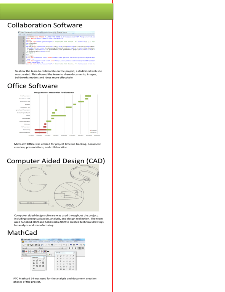
Collaboration Software To allow the team to collaborate on the project, a dedicated web site was created. This allowed the team to share documents, images, Solidworks models and ideas more effectively. Office Software Microsoft Office was utilized for project timeline tracking, document creation, presentations, and collaboration Computer Aided Design (CAD) Computer aided design software was used throughout the project, including conceptualization, analysis, and design realization. The team used AutoCad 2009 and Solidworks 2009 to created technical drawings for analysis and manufacturing. MathCad PTC Mathcad 14 was used for the analysis and document creation phases of the project. Bioreactor Fluid System Shady Adib, Jordan Barnett, Hideaki Inoue, Darius Respini-Irwin Sponsor: Dr. Sean S. Kohles, PSU Repairative Bioengineering Lab Advisor: Dr. Faryar Etesami Solid Modeling In this first stages of the design project we utilized Solidworks to render 3D models of our concepts as well as our final designs. This helped us better communicate our ideas in addition to being a quick and effective way to use engineering principles to check the design and assembly of our concepts. FEA (Finite Element Analysis ) In this phase we used Solidworks FEA software to analyze the stress distribution. There is an applied load on each sleeve and our team had to make sure that the loading from the force actuator would not cause a fracture or a crack in the component. Our results showed maximum stress concentration well below the allowable limits. CFD (Computational Fluid Dynamics) Another tool for analysis our group used was the Solidworks CFD software. A requirement for our project was that the waste fluid inside of the sleeve has to be replaced with the new nutrient fluid. The inside of sleeve shape was designed using CFD to minimize the recirculation of the fluid. Microcontroller Development & Circuit Design The pump controller utilizes an custom microcontroller system. Arduino IDE and AVR Studio were used to develop the firmware for mcu. Circuit design and layout was performed in Eagle CAD. MASTER CAM In the fabrication phase of our project we imported our Solidworks part models into the MASTERCAM X4 program. This allowed us to quickly create CNC programs for tool paths including contour, drill, and pocketing cuts. CNC The team utilized a two axis CNC machine in the PSU machine shop. It loads the MASTER CAM design, and it mills a material into the desired shape.


