Garmin G1000 avionics Special features Optional feature & system
advertisement
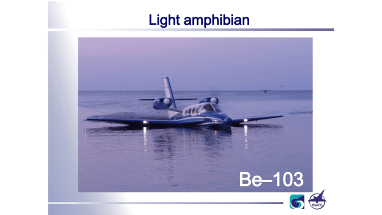
Light amphibian Be–103 General information on the Be –103 amphibian • The Be-103 amphibious airplane is an aircraft of normal category and intended for passengers and cargo transportation to the areas that are hardly to be reached by other transport systems — with a number of water areas. The airplane is able to perform the VFR flights day & night. • The Be-103 amphibian is a low-wing monoplane, monoplane with a draught wing provided with a root rib extension, with all-moving horizontal tail and tricycle landing gear with nose wheel. There are fixed slats arranged on the leading edge of the wings at the area of the ailerons. Implementation of the concept with draught wing providing capability of aquaplaning on three points (step, LH and RH wings trailing edges) gives a considerable advantages in stability on water and seaworthiness. 02 Cut-away view 03 General information on the Be –103 amphibian • The airplane is equipped with two TCM IO–360ES4 piston engines, certified by FAA, Type Certificate E1CE. The engines with power of 210 h.p. each are installed on the pylons from both sides of the fuselage aft and above rear part of the wing center section. Such a configuration prevents water strikes to propellers while taking off and landing on water. • Airframe design, layout, equipment and systems installed on the airplane meet the requirements of Part 23 of Russian Aviation Regulations for the airplanes of normal category and the Be–103 Certification basis, that considers amphibian operation features. 04 Certification The Be-103 has been certified under the AP-23 Russian Airworthiness norms for VFR flights: • The Type Certificate ST204–Bе–103; • The Supplemental Type Certificate No. SТ204–Bе–103/D1; • The Supplemental Type Certificate No. SТ204–Bе–103/D2; • The Supplemental Type Certificate No. ST204-Be-103/D3 • The Supplemental Type Certificate No. ST204-Be-103/D4 • The Type Certificate No. SSh 126–Bе– 103 to meet the noise requirements. The FAA Type Certificate No.A55CE for IFR flight operations under the FAR-23 (USA) norms was issued on July 11, 2003. The CTA Type Certificate No.2005T15 under the RBHA-23 (Brazil) norms was issued on August 03, 2005. The CAAC Validation of Type Certificate No.VTC173A under the China norms was issued on December 22, 2005. Now the aircraft is in the process of certification in Europe and Canada. Production The Certificate No. ОP 62-PVS on Approval of the Be-103 Production at KnAAPO was issued by the Aviation Register of the Interstate Aviation Committee on March 25, 2003. It was valid till June 25, 2005. New certificate, valid till May 31, 2007, was issued on May 31, 2005. In May, 2003 the Production approval was issued by USA aviation authorities, and in April, 2005 – by Brazil aviation authorities (CTA). 06 The Be-103 program development Receiving of the Type Certificate 26.12.2001 First flight 15.07.1997 Certification flight and life-time tests Manufacture of experimental aircraft 1995 Receiving of the Type Certificate under IFR, in the mid 2003 Aircraft deliveries to the customers Production Certification 1997 Manufacture of the experimental aircraft 1999 2001 2003 2005 2017 Certification, flight and life-time tests Production Certification First flight for certification under FAR.23 in the mid 1999 Aircraft deliveries to the foreign customers Receiving of the Type Certificate under FAR.23 May, 2003 – mid 2004 Main Suppliers VARTA (Germany) EMERGENCY ELECTRIC SYSTEM TELEDYNE CONTINENTAL MOTORS (USA) ENGINE AND ELECTRIC GENERATOR MT-PROPELLER GmbH (Germany) PROPELLER MICHELIN (France) TIRES and WHEELS ADAMS AVIATION SUPPLY COMP. (UK) NAVIGATION LIGHTS AND RESCUE EQUIPMENT GOODRICH (USA) POWERPLANT ICE PROTECTION SYSTEM BENDIX/KING (USA) AVIONICS Hawker GmbH (Germany) PUMPS of HYDRAULIC SYSTEM «NAUKA-VOSTOK» (Russia) HEATING AND VENTILATION SYSTEM Juhostroj (Czechia) и PARKER HANNIFIN CORP. (USA) FUEL PUMP TEKhPRIBOR (Russia) FUEL RESERVE MEASURING SYSTEM SCHROTH SAFETY PRODUCTS GmbH (Germany) SEAT BELTS «TOPAZ» (Russia) FLIGHT DATA RECORDING SYSTEM 07 Westberg (USA) INDICATORS and SENSORS SEGPO and KBE (Russia) NAVIGATION LIGHTS ELEKTROAVTOMATIK (Russia) ELECTRIC SYSTEM Deliveries The first three Be–103 amphibians had been delivered to Sky Manor Airport (Pittstown, New Jersey, USA) on August, 2003. Since 2004 two Be-103 aircraft are operated by KnAAPO Airlines. In 2005 two aircraft were delivered in Beriev TANTK. At the present moment 40 Be-103 aircraft are in production for delivery in 2006-2007 to customers from China, Cyprus and Brazil. 08 12,3 ft General view of the Be –103 amphibious aircraft 35,6 ft 41,7 ft 09 Weights 10 • Maximum taxi weight, kg (lb.) 2280 (5022) • Maximum take-off weight, kg (lb.) 2270 (4998) • Maximum useful load, kg (lb.) 420 (926) • Max. weight without fuel, kg (lb.) 2219 (4888) • Max. fuel weight, kg (lb.) 245 (540) • Maximum landing weight, kg (lb.) 2270 (4998) Speeds • VNE (Never Exceed), km/h (knots) • VNO (Structural cruising), km/h (knots) • VA (Maneuvering), km/h (knots) • VLE max. landing gear extension speed, km/h (knots) • VMC single engine minimum control speed • Rate of climb at sea level at takeoff weight of 2270 kg, m/s: — 2 engines operative — single engine operation • Lift-off speed, km/h (knots) • Landing speed, km/h (knots) 11 240 240 215 183 115 (130) (130) (116) (99) (62) 5.2 0.4 135–140 130–135 (17) (1.3) (72–75) (70–72) Dimensions Length (without radar), m (ft) Wing span, m (ft) Height, m (ft) Wing area, m2 (sq. ft) Fuselage length, m (ft) Fuselage maximum width, m (ft) Cabin length, m (ft) Cabin width, m (ft) Cabin height, m (ft) Cabin volume , m3 (ft3) Entrance and emergency doors , m (ft) Aircraft ground turn radius, m (ft) 12 10.65 12.72 3.76 25.1 9.96 1.35 3.2 1.25 1.23 4.6 m3 1.3 х 0.9 8.175 (35) (41.7) (12.3) 270.2 (32.7) (4.43) (10.5) (4.1) (4) (162) (4.3 х 3) (26.8) Limitations •Max positive operational maneuvering g-load •Max negative operational maneuvering g-load •Max operational flight altitude, m (ft) •Reserve remaining fuel, kg (lb) •Take-off and landing on water is prohibited at night. •It is prohibited to operate the aircraft under actual and predicted icing conditions (outdoor temperature lower +5°C if raining, drizzling or snowing). •It is prohibited to flight within thunderstorm area. 13 +3.45 -1.45 3000 (10000) 10 (33) Take-off Distances up to 50 ft (15 m) m ft 1220 4000 MSA, 3000 ft MSA+300, SL 1067 3500 914 14 3000 762 2500 609 2000 MSA, SL from water MSA, 3000 ft MSA+300, SL MSA, SL from ground 457 1500 305 1000 4100 4200 4300 4400 4500 4600 4700 4800 4900 5000 1860 1905 1950 1995 2041 2086 2132 2177 2222 2269 5100 lb 2313 kg Landing Distances from 50 ft (15 m) m ft 610 2000 595 1950 Ground landing MSA, 3000 ft MSA+300, SL 580 1900 564 1850 548 1800 533 1750 4100 1860 15 MSA, SL 4200 4300 4400 4500 4600 4700 4800 4900 5000 5100 lb 1905 1950 1995 2041 2086 2132 2177 2222 2269 2313 kg Payload – Range Lb. Kg 772 350 661 300 551 250 441 200 331 150 220 100 110 50 Payload Range 0 0 16 200 400 600 800 1000 1200 1400 108 216 324 432 540 648 756 1600 Km 864 n.mile Airdromes Airdromes : — airdrome elevation not more than, m (ft) — runway length not less than, m (ft) — max crosswind, m/s (knots) — max down wind — outside temperature 17 900 (3000) 1188 (3900) 6 (11.6) 2 (3.9) -30°C to +40°C Water Areas Water areas: — length not less than, m (ft) — width not less than, m (ft) — depth at rough water of 0.5 ft not less than, m (ft) — max wind wave height, m (ft) — max crosswind, m/s (knots) — max down wind, m/s (knots) — outside temperature at ground 18 1500 (5000) 100 (330) 1.5 (4.9) 0.4 (1.31) 3 (5.8) 0 +5°C to +40°C Basic Passenger Variant • Cabin capacity — 6 seats. • In the cabin there is a pilot’s working place and passengers’ seats per 2 in a row with central pass of 200 mm (8 in.), seats spacing of 1220 mm (47 in.) and 860 mm (34 in.). Passengers’ seats Pilot seat 19 Luggage compartment • In the front part of the cabin, the maritime equipment — anchor, line, hock and others — is located. • The back wall of a cabin separates it from a luggage compartment (capacity 0,8 m3 (28 cub.ft.). • In the aft part of the luggage compartment, the electrical and heating equipments are located. Passenger Cabin The cabin is equipped with six seats: one for pilot and five for passengers. The seats are located in three rows. There is a passage along the cabin to provide the passengers and pilots to enter, take the seats and go out of the aircraft between the seats. Each seat is equipped with a seat belt fixed to the seat and consisting of lap belt and two bandoliers having one lock. The seats of the first and third row can move by guide rails in longitudinal direction and can be fixed. Each seat can be dismantled without use of the tool, if required. 21 The Be-103 piloting and control • The aircraft piloting is accomplished by one pilot, controlling movable horizontal stabilizer, one pair of ailerons and rudder with trimmer. • The control stick and pedals are the command controls. • There is provision for installation Instructor’s dual controls at RH side. The forces from controls to control surfaces are transferred through push-pull control linkage in the longitudinal and lateral control channels and through cable linkage in the heading channel. • • • • 22 Movable horizontal stabilizer Rudder Aileron Rudder trim tab Aileron The servos of autopilot systems are connected to the linkage of lateral and longitudinal channels. Controllability is provided with spring-loading mechanism, with special loading diagram. This mechanism is connects the elevator horn with linear electrical mechanism, providing aircraft trim in longitudinal channel and emergency control in the case of disconnection (failure) of any linkage element. To provide control in the case of cable jamming in the longitudinal channel there is “expanding rod” device provided implemented with linear electrical mechanism. The rudder trim tab control is of electrical-mechanical type. Powerplant • Suppliers: TELEDYNE CONTINENTAL MOTORS (USA) and MT-PROPELLER GmbH (Germany) • Engine type: TCM IO-360 ES4 • Engine weight: Dry weight 158 kg 348 lb. Equipped engine 163,35 kg 360 lb. • Max. capacity (2800 rpm) 210 hp • Reliable engine start on ground and in flight at ambient air temperature of (-55°C) - (+ 45°C ) and at heights up to 3000 m / 9843 ft. • The engine has a standard flange for propeller fastening. • The engine is equipped with air-in system, ignition system, oil and fuel system • Type Certificate No. ST 84-D issued on 22.06.1996 by the Aviation Register of the Interstate Aviation Committee • FAA Type Certificate No.E1CE dated 28.09.1995 23 МТV-12-D-С-F-R(M)/CFR183-17 Propeller •Three-blade reversal variable pitch propeller. • Propeller diameter of 1,83 m (6 ft.). • Type Certificate No. ST 173-VV issued by the Aviation Register of the Interstate Aviation Committee on 17.11.1999 • FAA Type Certificate No. P–25NE dated 10.12.1999 24 The Be-103 amphibian fuel system Tanks No. 1 and 2 Tanks No. 3 and 4 Fuel system is composed of two autonomous system for LH and RH engine. These system are of similar design and connected with cross-feed valve. • The system is composed of the tanks, fuel tank venting, fueling, fuel transfer, fuel feeding to the engines, draining systems. Also there are implemented the indicating instruments and devices. • The tanks No. 3 and 4 are located in the wing center section. The tanks No. 1 and 2 are located in the pylon, these tanks are used as fuel consumed ones. • •The fuel system (fig. 5.3) provides adequate fueling and uninterruptible fuel supply to both engines in defined flight conditions within all the range of engine operation modes. • Fuel transfer system provides fuel transfer from wing tanks to the pylon ones. • The fueling is performed through the fillers arranged on the upper panels of the wings and the pylons. • Fuel feeding system provides fuel supply to the engines in all the conditions of engine operation modes. • There are drain valve installed on the lower panels of the tanks. 25 The Be-103 amphibian chassis • Landing gear is designed for operation from concrete and unpaved runways with strength б5 kgf/sq.cm • There are oil-nitrogen shock absorbers implemented in. • The nose leg is hinged to the airframe, equipped with wheel without brakes, with tire 400х150. Tire pressure is of 2.4+0.5 kgf/cm2. • Each main legs of the landing gear is provided with shock absorber hinged to the wing and equipped with the wheels with brakes, with tire of 476х178. Tire pressure is of 3.9+0.2 kgf/cm2. • Retraction and extension of the landing gear is performed with hydraulic jack actuated from the main airborne hydraulic system. The emergency operation of the landing gear is performed manually with cable linkage system – by opening the locks of closed landing gear position. Actuation of the landing locks in opened position is provided by weight forces and air dynamic forces of ram air. • The parking braking is provided. 26 Main leg Nose leg The Be-103 amphibian hydraulic system Feeding panel with the pump Hydraulic accumulator of the landing gear brakes system • Hydraulic system provides extraction and extension of the landing gear, main and parking braking of the wheels of the main legs. • Electrical hydraulic pump developed by Abex (Germany) is used as the pressure source in the hydraulic system. The hydraulic pump provides nominal pressure of 16.5 MPa (165 kgf/cm2). • The piston-type hydraulic accumulator is the pressure source for the brakes actuation while parked. The charging pressure of the nitrogen chamber of hydraulic accumulator is of 5.8-0.3 Mpa (58-3 kgf/cm2). • The operational liquid in the hydraulic system is of AMG-10, Russian Standard GOST 6794-75. 27 Cabin heating & ventilation Air intake (LH and RH) Air intake with regulator Electrical air heater • Heating and ventilation system provides comfortable and survival conditions for crew and passengers. • The heating & ventilation system provides the following: - cabin ventilation with outside air; - heating of the air supplied to cabin; - individual ventilation of pilots and passengers; - de-fogging of the front canopy area. 28 Electrical power supply system of the Be-103 amphibian • Electrical power supply systems provides functioning of the following airborne systems: - engine start; - engine operation monitoring; - fuel system and fuel measuring equipment; - navigation and radio/radar equipment; - communication equipment; - aircraft control system; - airborne record system; - icing indication; - lighting equipment; - landing gear retraction-extension and breaking systems. • • • 29 Generators Voltage regulator Storage battery Distribution device Rectifier Two AC generators with the rectifiers built-in are used as the main sources of electrical power on the airplane. The generators are produced by Teledyne Continental Motors, Part No. ТСМ 653344, with output power of 1.7 kW (60 A) each. The storage battery F20/17H1CT developed by “VARTA” is used as emergency power source. The battery capacity of 17 Ah. The output power of one generator is sufficient to provide electrical power to all the consumers in the case of failure of the other generator. The electrical power supply system is developed with fire-proof provisions. There is ground power connector provided in the airplane to supply the electrical power from ground source. The Be-103 amphibian lighting equipment • The lighting equipment components are divided into the following groups respect to functionality and arrangement : - navigation equipment; - landing & taxing equipment; - internal lighting equipment. • Navigation equipment is composed of wing flash and navigation lights A650-PG-28 and А650PR-28 developed by WHELEN, rear navigation light АНО3-Бл , and anchor light ОЯГ-1. • The red navigation light with wing flashing light A650-PR-28 is installed on the LH wing, and the green navigation light with wing flashing light A650-PG-28 is installed on the RH wing. • • • • 30 The rear navigation light АНО3-Бл is installed in the rear part of the tail tip. Anchor (parking) light is used when the airplane is parked on water anchored (in night conditions). The anchor light ОЯГ-1 is located on the top of the tail tip. There are two landing & taxi lights installed in the leading edges of LH and RH wings. The lights have part No. АПРФ-2. Internal lighting equipment provides the following: - lighting of instruments and system controls; - general lighting of pilot station; - warning indication at pilot station; - lighting of the passengers’ cabin and baggage compartment; - lighting of service compartments. Rear navigation light Anchor light Wing green navigation and flashing lights Cabin lights Lights Landing & taxiing lights Wing red navigation and flashing lights Radio communication equipment of the Be-103 amphibian • Radio communication equipment provides two-way radio communications with air traffic control, switching radio equipment and listening to the navigation signals. • The following equipment is defined for installation onboard: - KY196A VHF radio - 2 pcs.; - KMA 24 intercommunication equipment - 1 pc.; - headset - 1 pc.; - P-855A1 emergency VHF radio - 1 pc. VHF radio Emergency radio 31 Cockpit Instrument Panel-Garmin G1000 Avionics GDU-1044B Primary Flight Display (PFD) Control Wheel Push-ToTalk Switch-Pilot/Co-pilot GMA-1347 Digital Audio Panel with Marker Beacon/Intercom GDU-1044B Multifunctional Display (MFD) GTX-33 Transponder-Mode S w-TIS (Interfaced with MFD) Emergency Locator Transmitter Remote Mounted Switch Master and Alternator switch Alternate Static Source Avionics Switch Throttle (Push) Pitot (heated) & static system panel Backup Attitude Gyro, Altimeter, and Airspeed Indicator Mixture (pull) Handheld Microphone Auxiliary Stereo Input Jack Rudder Pedals 32 GRS-77 attitude and heading reference system (AHRS) GDC-74A Air Data Computer with OAT Probe GDU-1044B Primary Flight Display it uses solid-state sensors to measure aircraft attitude, rate of turn, and slip and skid Replaces the pitot-static systems in traditional aircraft instrumentations, it measures airspeed, altitude and outside air temperature GMU-44 Magnetometer LCD screens Can be switched it measures aircraft heading and is a digital version of a traditional compass GDU-1044B Multifunctional Display GEA-71 Engine/Airframe Computer It measures a large variety of engine and airframe parameters, including engine RPM, manifold pressure, oil temperature, cylinder head temperature, exhaust gas temperature, and fuel level in each tank GIA-63W NAV/COM/GPS/WAAS with GS Garmin G1000 avionics Special features • Garmin Safe Taxi & FliteCharts Garmin Safe Taxi Able to taxi around unfamiliar airports with ease. It identifies runways, taxiways, FBOs, hangars, and the aircraft’s exact location on the field. SafeTaxi is geo-referenced, pilots will benefit by seeing their aircraft icon move precisely along the taxiway diagram Garmin FliteCharts An electronic version of the National Aeronautical Chart Office (NACO) U.S FliteCharts allows pilots to quickly find and view all NACO Departure Procedures (DP), Standard Terminal Arrival Routes (STARs), approach charts, and airport diagrams on the MFD. Garmin G1000 avionics Special features • GTX 33 S mode Transponder • Fuel Range Ring Integrated on the Multifunctional Display shows the aircraft’s range given its current ground speed and fuel burn. Displays Traffic Information System (TIS-A) alerts. provides mode-S bidirectional communications with Air Traffic Control It can indicate traffic in the area as well as announce itself spontaneously via "squittering" without prior interrogation. Remote Ident and auto standby capability Provide a dashed-line ring inside the absolute (tanks dry) range ring that shows how far you can fly and still have a certain endurance of fuel still in the tanks Prevents accidents from fuel exhaustion Garmin G1000 avionics Special features Electronic Checklists An automatic-sensed checklist A safety & warning supplement system Shows important system messages & status provide a final check that the aircraft has been properly configured for each phase of flight Shows failure & Warning messages. Garmin G1000 avionics Special features Optional feature & system Garmin Synthetic Vision Technology Provide sophisticated graphics modelling of terrain, traffic and obstacles in the flight path. The system looks at the entire flight via satellite and renders a 3D landscape. Inscriptions Inscriptions on external surface of the aircraft, in pilot’s cockpit and cabin are carried out by agreement with a customer in a language specified in the sale contract. The external inscriptions includes information for ground maintenance and inspection as well as warnings and cautions. The external inscriptions on operational hatches are intended for indication of access to the aircraft systems. They indicate the following: • points of fueling and operating fluid discharge; • access to units and assemblies of the systems. To provide personnel safety, the areas of safe access are indicated on the wing. Internal inscriptions include information required for internal general and emergency information, instructions, warnings and cautions. 33 Aircraft service life and lifetime • Design assigned service life, flight hours…………………….…………….. 15000 • Assigned Service life: - landings on the ground (including unpaved fields)………………………. 6000 5000 - landings on water……..………………………………………….......….….. • The activities to increase number of landings within assigned service life should be performed during development and operation of the airplane. 20 • Calendar lifetime, years………………………………………………………. 34 Maintenance Features • on maintenance condition • use of the built-in test system • easy access assemblies and units • full capability to autonomous That provides: • high level of aircraft readiness (pre-flight preparation is performed during 10 minutes) • prompt failures discovery • reduce of operation costs • maintainability 35 Ground Towing Ground towing within the airdrome as well as roll in and out of the water is carried out by means of a tow car. 36 Water Towing Water towing can be carried out at wind speed not more than 15.5 knots (8 m/s) and wave height up to 1.6 ft (up to 0.5 m). The aircraft is towed by nose towing ducks of the aircraft with the help of a tow cable. 37 Parking and Mooring During parking, the aircraft should be deenergized, the controls should be stopped and the accumulators should be taken away for long parking (for more than 24 hours). A set of mooring devices, chokes and safety support are used to prevent the aircraft from accidental movement during parking on the slope area, at gust and engine run-up operations. Mooring devices provide holding of the aircraft at wind speed up to 78 knots (40 m/s) A safety support is provided to prevent the aircraft from fall to the tail. 38 List of technical documents applicable to the Be-103 • Operational document sheet • Aircraft logbook • Engine logbook with certificates for assemblies and purchased items installed in engine • Maintenance manual for engine, its systems and assemblies • Certificates for assemblies and purchased items • Flight operation manual. • Load and center of gravity manual. • Maintenance manual • Maintenance schedule • Electric circuit diagram manual • Maintenance manual for purchased items installed in the aircraft. • Spare parts lists, list of tools, list of ground support equipment, list of ground test equipment. • Acts and measuring tables • Aileron, horizontal stabilizer and rudder balancing manual 39 Regional Agent King Join International Pte Ltd 京华国际有限公司 1, North Bridge Road, #16-08 High Street Centre, Singapore 179094 Tel: 65-63388707 Fax: 65-63388929 Email: rreg1988@regalindo.com.sg Mr. 1988@regalindo.com.sg 40


