Axial, Shear Force & Bending Moment Diagrams Explained
advertisement
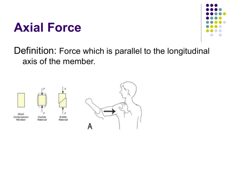
Axial Force Definition: Force which is parallel to the longitudinal axis of the member. Shearing force Definition: Force which is perpendicular to the longitudinal axis of the member. Shearing force Shearing force The shearing forces at the end of the beam is equal to the vertical reaction at the support. The shearing force F(x) at any other section “x” on the beam can be found by using the following equation. Shearing force L q kN/m V= F(x) x R1 Bending Moment Definition: Turning effect of a force can be called as bending moment. M L Axial Force, Shear Force and Bending Moment Diagram To determine the change in internal forces along the length of the beam or frame To determine the location of maximum stress caused by these internal forces To ensure that this stress must remain with in elastic limit Axial Force, Shear Force and Bending Moment Diagram How to draw internal force, shear force and bending moment diagram Take an imaginary cut at any point along the length of beam and frame Draw the free body diagram Calculate the magnitude of these forces using equations of equilibrium Axial Force, Shear Force and Bending Moment Diagram Methods: To draw internal force, shear force and 1. 2. bending moment diagram Basic Method Integration or graphical method Fundamental Principle: 1. 2. The basic function representing shearing force or bending moment is developed This function is plotted along the length of the member Axial Force, Shear Force and Bending Moment Diagram Sign Convention: + Positive 1. 2. - Negative Shearing force that tends to rotate the free body in clock wise direction is positive Shearing force that tends to rotate the free body in anti-clock wise direction is negative Axial Force, Shear Force and Bending Moment Diagram Sign Convention: + Positive 1. 2. - Negative Bending Moment that tends to produce sag in the beam is positive Bending Moment that tends to produce hog in the beam is positive Axial Force, Shear Force and Bending Moment Diagram Procedure of Basic Method: 1. 2. 3. 4. Calculate the reactions at supports of the beam Take an origin for a co-ordinate x along the length of the beam. Cut the beam with an imaginary cut at a distance x, and draw the free-body diagram. Calculate the shear force and bending moment as a function of x using equilibrium equations. Shearing force diagram Shear force diagram is plots of the shearing force (on the vertical-axis) versus The position of various sections along the length of the beam (on the Horizontal-axis). Bending Moment Diagram Bending moment diagram is plots of the bending moment (on the vertical-axis) versus The position of various sections along the length of the beam (on the Horizontal-axis). Bending Moment and shearing force Diagram Class Notes Axial Force, Shear Force and Bending Moment relation ship Class notes


![Applied Strength of Materials [Opens in New Window]](http://s3.studylib.net/store/data/009007576_1-1087675879e3bc9d4b7f82c1627d321d-300x300.png)
