OddballERPInstructions2013
advertisement
Updated 3/14/2016
BSL PRO Lesson H09: Oddball Event-Related Potentials (ERP)
Objectives
1. To present an auditory stimulus to a human subject.
2. To record Event-Related Potentials (ERP).
3. To measure the effects of an oddball stimulus on the P300.
Equipment
PC running Windows
BIOPAC Software: Biopac Student Lab PRO
BIOPAC Data Acquisition Unit (MP36)
BIOPAC STP35A trigger Cable
BIOPAC Disposable electrodes (EL503)
BIOPAC Electrode lead set (SS2L)
BIOPAC Abrasive pads (ELPAD)
BIOPAC Electrode gel (GEL1)
Alcohol swabs
Nylon swim cap or bandage
Set-up
(Should be already set up, but be sure to check and make sure that things are set up properly)
Hardware:
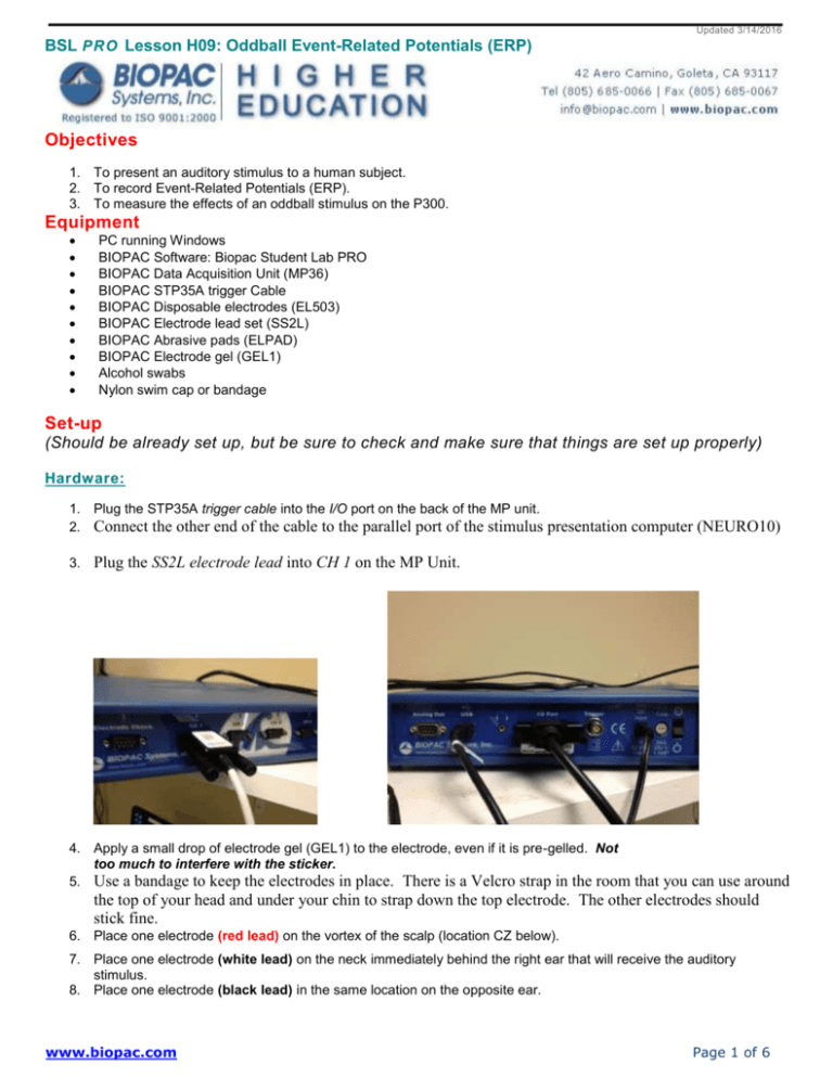
1. Plug the STP35A trigger cable into the I/O port on the back of the MP unit.
2. Connect the other end of the cable to the parallel port of the stimulus
3.
presentation computer (NEURO10)
Plug the SS2L electrode lead into CH 1 on the MP Unit.
4. Apply a small drop of electrode gel (GEL1) to the electrode, even if it is pre-gelled. Not
too much to interfere with the sticker.
5. Use a bandage to keep the electrodes in place. There is a Velcro strap in the room
that you can use around
the top of your head and under your chin to strap down the top electrode. The other electrodes should
stick fine.
6. Place one electrode (red lead) on the vortex of the scalp (location CZ below).
7. Place one electrode (white lead) on the neck immediately behind the right ear that will receive the auditory
stimulus.
8. Place one electrode (black lead) in the same location on the opposite ear.
www.biopac.com
Page 1 of 6
Participant Set-up:
Data Recording:
5. Turn on the Data Collection computer (NEURO9 – will run BIOPAC) and the stimulus presentation computer
(NEURO10 – will run E-PRIME).
6. Turn on the MP36 Data Acquisition Unit.
7. Launch the BIOPAC BSL 4.0 MP36 software on the NEURO9 computer.
8. Open the Oddball template by choosing Open graph template from disk … >{click ok} choose Files of type:
GraphTemplate (*GTL) > File Name: OddballDataAcquisition.gtl (located on the desktop)
www.biopac.com
Page 2 of 6
9. Your data collection window will now open and look like the image below.
F
ile Name: OddballDataAcquisition.gtl (graph template) windows when file is opened
10. If the start button is not green as in the picture above, go to M36 and choose “check for hardware”
11. Go to File-Save As and save the file as your name (.acq file) – Note: It does NOT save automatically!
12. The signal on the screen should have variability in the top ERP channel and the bottom three lines should be flat. It
is important that the subject be keeping very still as any movement during the recording will introduce artificial noise
into the signal. The top channel of the image below shows an incorrect signal (noisy). The bottom picture
shows a correct signal. The sine-wave signal show in the red channel indicates that the electrode on the left side
was not making good contact with the scalp.
www.biopac.com
Page 3 of 6
INCORRECT SIGNAL:
Correct Signal
****If you do not have a good signal, then you need to make sure that the EEG electrodes are making good contact with the
scalp, that you have filled the electrodes with the appropriate amount of gel, and that the ear reference electrodes are properly
in place. You may need to adjust the tightness of the strap that holds the electrodes in place.****
www.biopac.com
Page 4 of 6
Start Recording:
13. Once, you are happy with the quality of the signal, you can open the E-Prime program on NEURO10. Open the
EPrime program entitled “Oddball” on from the desktop. Instructions should appear on the screen. (READ THE
INSTRUCTIONS, BUT DO NOT PRESS THE SPACE BAR YET)
14. Click on the Start button in the BSL window to begin recording data.
PLEASE NOTE:
Participant should stay as still as
possible during the recording and
minimize blinks.
15.
16.
17.
18.
Press the space bar on NEURO10 to start the EPrime program.
The participant should sit very still and listen to the stimuli and make button presses as necessary.
When done recording, press stop on the BIOPAC program and save the data as your name and ATTENTION.
Then set up the second condition. This time you will ignore the instructions on the E-Prime program. Ignore the
tones and do not count them. On NEURO09 bring up the Youtube video that is bookmarked (Mr. Bean at the
Beach: youtube.com/watch?v=ZWCSQm86UB4). Make sure that the sound is off. Then press Start on BSL and
start EPrime at the same time and then press start on the Youtube video (the timing on that is not important). Pay
attention to the movie and ignore the tones.
19. When you are done save this file as your name and DISTRACTION.
Data Analysis
1. Click the horizontal autoscale icon (on the toolbar) to show all of the experimental data. Your graph should look
like the example below.
2.
3.
You will need to create an averaged waveform for the common stimuli and for the uncommon stimuli.
First, you will average the common stimuli. Click on the Analysis menu and choose Find Cycle.
www.biopac.com
Page 5 of 6
4. In the Cycle Detector box on the Cycles/Peak tab make sure that CH20, Digital input is selected and the
Threshold Level is : 4 Volts.
www.biopac.com
Page 6 of 6
4. In the Selection tab, choose Current Threshold and under Left Edge type +0.1 second (we will be averaging from
100ms before each stimulus). Under Right Edge type + 0.5 second (we will be averaging for 500ms after each stimulus)
5.
In the Output tab, choose Averaging Tab and click the box for Construct an average from: CH1, EEG
www.biopac.com
Page 7 of 6
6. Now click Find All Cycles which will find each trigger sent by EPrime after the common stimulus and will average
the brain activity for the next 0.5 seconds. A new ERP graph will be generated. If a warning that “no cycles were
found” occurs then just click ok.
7. Save this file as “Common Average of NAME_ATTENTION”
8. Now start from step #4 again, except in the Cycle Detector box on the Cycles/Peak tab make sure that CH21,
Digital input is selected in order to choose the uncommon stimulus.
9. Repeat these steps for the distraction condition.
www.biopac.com
Page 8 of 6
Peak Amplitude
The measurements should already be set as seen above.
5. Using the I-beam tool, to select the beginning of the wave to find the peak amplitude between 300 and 400 ms.
6. Then measure the area between 300 and 400 ms.
7. Measure the time of the peak amplitude between 300 and 400 ms.
8. Using the I-beam tool, to select all of the data to find the overall peak amplitude. (In the above example the peak
amplitude is the same as the overall peak amplitude, but that will not always be the case.)
When you are done clean up all other supplies and close BIOPAC. Turn off the power to the BIOPAC recording unit
and the stimulation unit. Leave the computers on. Then carefully clean electrode.
www.biopac.com
Page 9 of 6
