Venturi Lab
advertisement

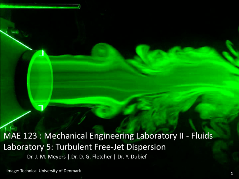
MAE 123 : Mechanical Engineering Laboratory II - Fluids Laboratory 5: Turbulent Free-Jet Dispersion Dr. J. M. Meyers | Dr. D. G. Fletcher | Dr. Y. Dubief ME 123: Mechanical Engineering Lab II: Fluids Image: Technical University of Denmark Laboratory 5: Turbulent Free-Jet Dispersion 1 Self Similarity • A similarity solution is one in which the number of independent variables is reduced by at least one, usually by a coordinate transformation • Normally, coordinates are collapsed into dimensionless groups that scale the velocities • One can take advantage of self-similar solutions to achieve useful simplifications in solving problems or comparing data from other experiments. Blasius solution for the flat plate boundary layer • Solid line is theory • Data points represent experiments at different Reynolds numbers ME 123: Mechanical Engineering Lab II: Fluids Laboratory 5: Turbulent Free-Jet Dispersion 2 Free Shear Flow Free shear flows are flows unaffected by walls and develop and spread in an open ambient fluid Pipe flow (wall bounded flow) Free jet flow (free shear flow) Velocity gradients in 𝑦 are created by some upstream mechanism, that are smoothed out by viscous diffusion in the presence of convective deceleration Because of the lack of wall confinement, the static pressure field is constant unlike in wall confined flows: 𝜕𝑃 𝜕𝑃 Pipe Flow =0 ≠0 𝜕𝑦 𝜕𝑥 Free Shear Flow ME 123: Mechanical Engineering Lab II: Fluids Laboratory 5: Turbulent Free-Jet Dispersion 𝜕𝑃 =0 𝜕𝑦 𝜕𝑃 =0 𝜕𝑥 3 Free Shear Flow Shear flow satisfies the flat plate equations (this is for 2D plane flow but arguments hold for axisymmetric as well) 𝜕𝑢 𝜕𝑢 + =0 𝜕𝑥 𝜕𝑦 𝜕𝑢 𝜕𝑢 𝜕2𝑢 𝑢 +𝑣 ≈𝜈 2 𝜕𝑥 𝜕𝑦 𝜕𝑦 Continuity Steady state 𝑥-momentum • Figure above shows two parallel uniform streams of two different velocities meeting at 𝑥 = 0 • As we move downstream the initial discontinuity imposed is smoothed out by viscosity into as Sshaped free-shear layer • The simplest application would be for 𝑈2 = 0 which would represent a jet emerging from a slot (recall we are thinking in terms of 2D plane flow for simplicity!) into ambient air at rest ME 123: Mechanical Engineering Lab II: Fluids Laboratory 5: Turbulent Free-Jet Dispersion 4 Free Shear Flow • We can generalize this into two different fluids with properties (𝜌1 , 𝜇1 ) and (𝜌2 , 𝜇2 ) • A self-similarity variable for each stream can be defined as: 𝑈 𝜂𝑗 = 𝑦 2𝑥𝜈𝑗 𝑓′𝑗 = 𝑢 𝑈𝑗 ME 123: Mechanical Engineering Lab II: Fluids Laboratory 5: Turbulent Free-Jet Dispersion 5 Free Shear Flow Free turbulence just refers to high Reynolds number shear flow in an open fluid environment unconfined by rigid boundaries Some common types include: a) A mixing layer between two streams of different velocity b) A jet issuing into a still stream c) A wake behind a body ME 123: Mechanical Engineering Lab II: Fluids Laboratory 5: Turbulent Free-Jet Dispersion 6 Turbulent Flow Reynolds decomposition refers to separation of the flow variable (like velocity ) into the mean (timeaveraged) component, 𝑢 𝑥 , and the fluctuating component, 𝑢′(𝑥, 𝑡). 𝑢 𝑥, 𝑡 = 𝑢 𝑥 + 𝑢′(𝑥, 𝑡) absolute mean velocity velocity velocity fluctuation The RANS (Reynolds Average Navier-Stokes) equations are primarily used to describe turbulent flows. These equations can be used with approximations based on knowledge of the properties of flow turbulence to give approximate time-averaged solutions to the Navier-Stokes equations. How does one measure mean and fluctuating velocities? 𝑢′(𝑥, 𝑡) Recall how in the pipe flow labs manometer fluctuations were higher toward the wall… this is where higher turbulence is present. ME 123: Mechanical Engineering Lab II: Fluids Laboratory 5: Turbulent Free-Jet Dispersion 𝑢 𝑥 7 Turbulent Free Jet • • • • • This figure shows the details of turbulent jet formation in still ambient fluid similar fluids (𝑘 = 1) (1) Near the orifice exit the jet issues at a nearly flat, fully developed, turbulent velocity 𝑈𝑒𝑥𝑖𝑡 (2) Mixing layers form at exit lip and grow toward the end of the inviscid potential core (about 1 orifice diameter, 𝐷, downstream) (3) After the core extinguishes the flow develops into a distinctive Gaussian-shaped “jet” (4) Finally, after a distance of about 20 × 𝐷 downstream the velocity profile reaches and maintains a self-preserving (self-similar) shape (1) ME 123: Mechanical Engineering Lab II: Fluids Laboratory 5: Turbulent Free-Jet Dispersion (3) (4) (2) 8 Turbulent Free Jet For an axisymmetric jet the self-similar shape takes on the following form: 𝑢 𝑈𝑚𝑎𝑥 ≈𝑓 𝑟 𝑏 The jet width, 𝑏, above may also have the notation of 𝛿 later in your notes or lab handout. It is the asymptotic self-similar form of free turbulent flows that we wish to study. (3) (1) ME 123: Mechanical Engineering Lab II: Fluids Laboratory 5: Turbulent Free-Jet Dispersion (2) (4) 9 Turbulent Free Jet Mass Flow • It is important to note that mass flow is not conserved in each velocity profile as flow is entrained and entering the system. THIS IS A SIGNIFICANT DIFFERENCE BETWEEN FREE SHEAR AND CONFINED PIPE FLOW 2𝜋 ∞ 𝑚(𝑥) = 𝜌𝑢 𝑥 𝑟𝑑𝑟𝑑𝜃 ≠ const 0 −∞ (3) (1) ME 123: Mechanical Engineering Lab II: Fluids Laboratory 5: Turbulent Free-Jet Dispersion (2) (4) 10 Turbulent Free Jet • Momentum Since there is no pressure gradient the jet momentum , 𝐽, must remain constant at each cross section. For an axisymmetric jet: 2𝜋 𝑀(𝑥) = 0 • ∞ 𝜌𝑢2 (𝑥, 𝑟, 𝜃)𝑟𝑑𝑟𝑑𝜃 = const = const × 𝜌𝑏 2 𝑈𝑚𝑎𝑥 2 −∞ In the self-similar region the centerline velocity should only depend on jet momentum, density, and distance… NOT viscosity (as there are no rigid boundaries… i.e. walls) 1/2 𝑀 𝑈𝑚𝑎𝑥 = const × 𝑥 −1/2 𝜌 (3) (1) ME 123: Mechanical Engineering Lab II: Fluids Laboratory 5: Turbulent Free-Jet Dispersion (2) (4) 11 Turbulent Free Jet Kinetic Energy • The flux of mean kinetic energy is not conserved 2𝜋 𝐾(𝑥) = 0 ∞ 𝑢2 (𝑥, 𝑟, 𝜃) 𝜌𝑢(𝑥, 𝑟, 𝜃) 𝑟𝑑𝑟𝑑𝜃 ≠ const 2 −∞ (3) (1) ME 123: Mechanical Engineering Lab II: Fluids Laboratory 5: Turbulent Free-Jet Dispersion (2) (4) 12 Theoretical Models of Self-Similar Solutions Görtler Theory 𝑢 𝑈𝑚𝑎𝑥 𝜂2 ≈ 1+ 4 −2 𝜂 ≈ 15.2 𝑦 𝑥 Eq. 6-152 Plane Jet Solution Variation: 𝑢 𝑈𝑚𝑎𝑥 ≈ sech2 10.4 𝑦 𝑥 Eq. 6-153 Average velocity These are analyzing the time averaged mean velocity: 𝑢 𝑥, 𝑡 = 𝑢 𝑥 + 𝑢′(𝑥, 𝑡) absolute mean velocity velocity velocity fluctuation The time-averaged velocity, 𝑢 𝑥 , approaches a self similar state wll before the turbulent velocity fluctuation contribution, 𝑢′(𝑥, 𝑡) How could you measure the level of turbulence? ME 123: Mechanical Engineering Lab II: Fluids Laboratory 5: Turbulent Free-Jet Dispersion Turbulent velocity 13 Free Jet Experiment • • Density must be constant over the whole flow domain From the Venturi lab, we had one known quantity, which was the total pressure of the working fluid was the atmospheric pressure since laboratory air was drawn into the wind tunnel: 𝑃𝑡𝑜𝑡𝑎𝑙 = 1 atm for Venturi lab • • • Static pressure values (measured by hydrostatic devices, manometers) decreased as velocity increased and vica versa as dictated by the Bernoulli relation These principles hold for a free jet experiment but the working conditions are different. For this experiment, air enters the pipe, is compressed, and then is ejected as a free jet into the lab ME 123: Mechanical Engineering Lab II: Fluids Laboratory 5: Turbulent Free-Jet Dispersion 14 Free Jet Experiment • Now we are working at the exit of a compressor rather than at the entrance like we did with the wind tunnel • What does the compressor do to the working fluid? • Increase Pressure • The jet flowing into still air entrains some of the surrounding air and causes it to have forward momentum, but the entire flow is subjected to a constant pressure boundary condition imposed by the medium it enters… • Will this fluid (air) leaving the jet have a pressure greater or less than ambient? • Static pressure is equal to the atmospheric pressure • Total pressure will increase due to velocity and is not equal to atmospheric in this lab ME 123: Mechanical Engineering Lab II: Fluids Laboratory 5: Turbulent Free-Jet Dispersion 15 Free Jet Experiment • The Pitot probe for this lab is designed specifically for incompressible flow applications to measure total pressure • We will be using a different Pitot probe but the same manometer setup as the last lab. • By now you should feel confident with the hydrostatic force balance on the manometer fluid and how to extract velocity • The Pitot probe has only one opening at the tip. The jet is flowing in the ambient air where the density is taken to be constant • As with the Venturi experiment the total pressure is nearly constant… but is the total pressure the same as it was for the wind tunnel? Why or why not? • Please address this in your report. ME 123: Mechanical Engineering Lab II: Fluids Laboratory 5: Turbulent Free-Jet Dispersion 16 Free Jet Experiment • • • • • A diagram of such a flow is shown below where a jet exits from a slot in a plane wall and draws fluid along because of what fluid property? If we measure the mass flow in the axial direction away from the jet, we find that this is not constant. How can we show this? However, we find that the total momentum is conserved in the axial direction. How can we show this? Kinetic energy will also not be conserved. How can we show this? How would a 2-D jet (planar) vs. an axisymmetric jet differ? Or are they similar? Why? ME 123: Mechanical Engineering Lab II: Fluids Laboratory 5: Turbulent Free-Jet Dispersion 17 Free Jet Experiment • • • • We will measure the Pitot pressure as a function of radial position at a number of axial locations POTENTIALLY for D = 30 mm: x/D = 1, 3, 5, 7 , 15, and 22 We are looking for a velocity profile development and for a self-similar region The velocity profile comes from the entrainment of the air Conservation of momentum suggests that: ∞ 𝑀= 𝑑 𝑑𝑥 𝜌𝑢2 𝑑𝐴 = const = const × 𝜌𝑏 2 𝑈𝑚𝑎𝑥 2 −∞ • ∞ 𝑢2 𝑥, 𝑦 𝑑𝑦 = 0 −∞ In the self-similar region, we can express velocity as: 𝜂= 𝑢 𝑥, 𝑦 = 𝑢0 𝑥, 𝑦 𝑓(𝜂) Where: 𝑦 𝛿(𝑥) 𝑑𝑦 = 𝛿 𝑥 𝑑𝜂 ME 123: Mechanical Engineering Lab II: Fluids Laboratory 5: Turbulent Free-Jet Dispersion 18 Free Jet Experiment • In the self similar region, this shape factor is constant: 𝑑 𝑈0 𝑥, 𝑦 2 𝛿 𝑥 𝑑𝑥 ∞ 𝑓(𝜂)𝑑𝜂 = 0 −∞ 𝑑 𝑈0 𝑥, 𝑦 2 𝛿 𝑥 = 0 𝑑𝑥 • So the integral is also constant, so we realize that: • Your task is to measure the parameter defining the jet width, 𝛿 𝑥 , which we can define as the distance where the local value of velocity is 5% of the centerline Then with the centerline velocity value, give the region of the jet where this relation holds (identify the measurement locations where this relation is valid) Keep in mind what the Pitot probe is measuring! Interpret your measurements and your conclusions considering propagation of error. • • • ME 123: Mechanical Engineering Lab II: Fluids Laboratory 5: Turbulent Free-Jet Dispersion 19 Free Jet Experiment The blower section with attached orifice plate at the end of the pipe flow facility will act as your experimental apparatus A Pitot probe is attached to a 3-axis translating support with built-in measurement scales to facilitate velocity profile measurements 𝒛 At each measurement point in your profile you need only to record total pressure and atmospheric pressure heights from the manometer. Velocity, as you are very familiar in calculating, will come from the known relation: 𝑃𝑡 = 1 2 𝜌𝑢 + 𝑃𝑠 2 𝑢= 2 𝑃𝑡 −𝑃𝑠 𝜌𝑎𝑖𝑟 What is the static pressure in this case? 𝒚 𝒙 Why is the total pressure not the atmospheric pressure? ME 123: Mechanical Engineering Lab II: Fluids Laboratory 5: Turbulent Free-Jet Dispersion 20 Free Jet Experiment For this lab you will measure radial velocity profiles of a jet exiting a 30 mm orifice at a sufficient number of chosen axial locations 𝒛 These surveys must be capable of addressing • evidence of entrainment • mass flow evolution in the x-direction (numerically integrate slide 10) • evidence of the conservation of momentum (numerically integrate slide 11) • a study of the evolution of kinetic energy (numerically integrate slide 12) You are also required to study, within the range of measurement by the apparatus, any evidence of self-similar behavior 𝒚 An appropriate uncertainty and sensitivity analysis of your results is also required ME 123: Mechanical Engineering Lab II: Fluids Laboratory 5: Turbulent Free-Jet Dispersion 𝒙 21


