VELOCITY AND MOTION SENSORS
advertisement

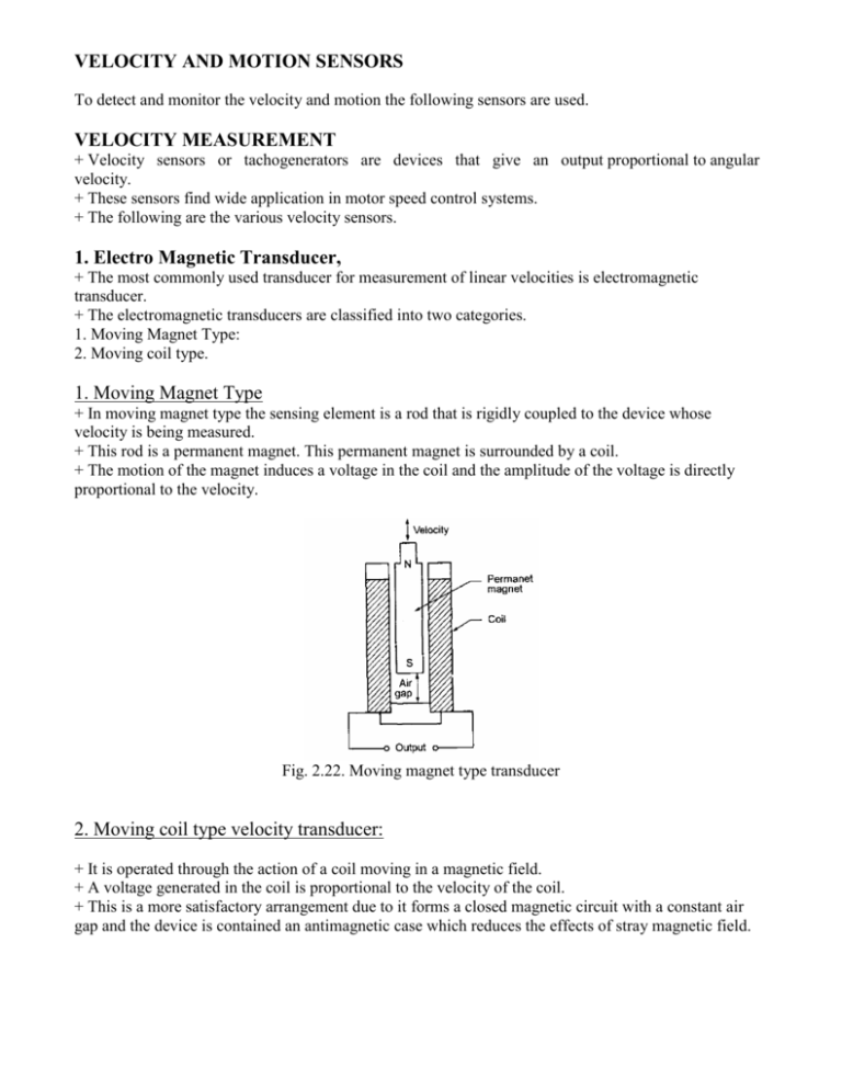
VELOCITY AND MOTION SENSORS To detect and monitor the velocity and motion the following sensors are used. VELOCITY MEASUREMENT + Velocity sensors or tachogenerators are devices that give an output proportional to angular velocity. + These sensors find wide application in motor speed control systems. + The following are the various velocity sensors. 1. Electro Magnetic Transducer, + The most commonly used transducer for measurement of linear velocities is electromagnetic transducer. + The electromagnetic transducers are classified into two categories. 1. Moving Magnet Type: 2. Moving coil type. 1. Moving Magnet Type + In moving magnet type the sensing element is a rod that is rigidly coupled to the device whose velocity is being measured. + This rod is a permanent magnet. This permanent magnet is surrounded by a coil. + The motion of the magnet induces a voltage in the coil and the amplitude of the voltage is directly proportional to the velocity. Fig. 2.22. Moving magnet type transducer 2. Moving coil type velocity transducer: + It is operated through the action of a coil moving in a magnetic field. + A voltage generated in the coil is proportional to the velocity of the coil. + This is a more satisfactory arrangement due to it forms a closed magnetic circuit with a constant air gap and the device is contained an antimagnetic case which reduces the effects of stray magnetic field. Fig. 2.23. Moving coil type velocity transducer 2. Tachogenerators: + A sensor that converts speed of rotation directly into electrical signal is called a tachogenerator. + It is used to convert angular speed into a directly dependent voltage signal. (a) Toothed Rotor Variable Reluctance Tachogenerator: + It is used to measure angular velocity. + This tachogenerator consists of a metallic toothed rotor mounted on the shaft whose speed is to be measured. + A magnetic pick up is placed near the toothed rotor and this magnetic pick up consists of housing, and the housing containing a small permanent magnet with a coil wound around it. + When the rotor rotates, the reluctance of the air gap between pickup and the toothed rotor changes and the rise in e.m.f. is induced in the pickup coil. Finally the output is in the form of pulses and wave shapes. + The pulses induced depend upon the number of teeth in the rotor and the rotational speed. When the speed is known, the rotational speed is calculated by measuring the frequency pulses. + Fig. 2.24. Toothed rotor tachometer generator + Suppose the rotor has ‘ n’ teeth and the speed of rotation is ‘ N’ r.p.s. and number of pulses per second is ‘ p’ . + The number of pulses per revolution = ‘ n’ = n The advantage of toothed rotor variable reluctance tachogenerator is the information from this device can be easily transmitted and easy to calibrate. 3. A. C. Generator Form of Tachogenerator: + It consists of rotor, which rotates with the rotating shaft and a coil. + When the coil rotates in the magnetic field the e.m.f. is induced. + The magnet may be in the form of stationary permanent magnet or electromagnet. + The frequency of this alternating e.m.f. is used to measure the angular velocity. + The output voltage is rectified and it is measured with a permanent magnet moving coil (PMCC) voltmeter. Fig. 2.25. A.C Tachometer generator MOTION SENSORS 1. Stroboscope: + Stroboscope is a simple portable manually operated device for periodic or rotary motions measurement. + It is a variable frequency flashing light instrument and the flashing is set by the operator. + If a strong light is caused to flash on a moving object at the time each flash occurs. The stroboscope occupies a given position, and the object will appear to be stationary. + The flashing light whose frequency can be varied and controlled, and this source is called strobotron. 2 Pyroelectric Sensors: + It consists of a polarised pyroelectric crystal with thin metal film electrodes on opposite faces. (Pyro electric materials, e.g., lithium tantalate are crystalline materials which generate charge in response to heat flow. When such materials heated to about 610° C in an electric field, the electric dipoles within the material line up and it becomes polarised as shown in Fig.). + Due to the crystal is polarised with charged surfaces, the ions are drawn from the surrounding air and electrons from any measurement circuit is connected to the sensor to balance the surface charge as shown in Fig. + For measurement of a human or heat source motion, the sensing element has to differentiate between general background heat radiation and a moving heat source. For that a single pyroelectric sensor is not capable to use and dual pyroelectric sensors are used as shown in Fig. + In this dual pyroelectric sensors the sensing element has the one front electrode and two back electrodes. When two sensors being connected means both sensors are receive the same heat signal and their outputs are cancelled. Fig. 2.26. Pyroelectric sensors + Suppose a heat source moves from its position means the heat radiation moves from one of the sensing elements to the other, then the current is alternates in one direction first and then reversed to the other direction second. + A moving human gives an alternating current of 1O A. When the infrared radiation is incident on the dual pyroelectric sensor material and changes its temperature, the polarisation in the crystal is reduced. A focusing device is needed to direct the infrared radiation onto the sensor.


