Electronic Lab Diagnostics Analysis Report Sample
advertisement

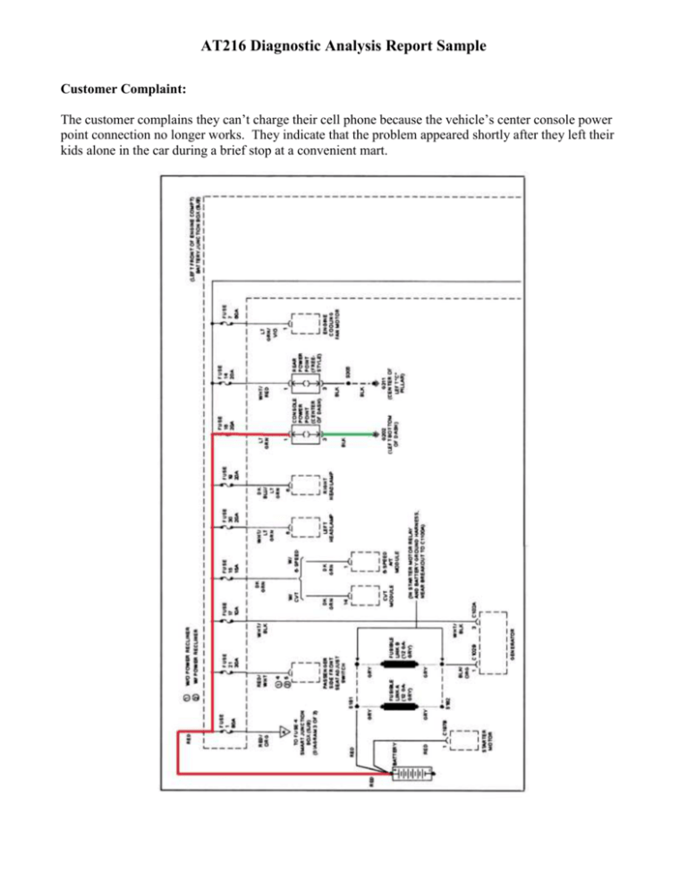
AT216 Diagnostic Analysis Report Sample Customer Complaint: The customer complains they can’t charge their cell phone because the vehicle’s center console power point connection no longer works. They indicate that the problem appeared shortly after they left their kids alone in the car during a brief stop at a convenient mart. John DOE AT216-01 Automotive Electrical Lab April 16, 2012 Diagnostic Analysis Report #1 The customer complains he can no longer charge his cell phone in his car because the center console power point outlet in his vehicle no longer works. The problem appeared shortly after he left his kids unattended in the vehicle for a short period. The center console power point outlet circuit is a simple series circuit protected by Fuse 16, a 20 amp fuse located in the battery junction box. This fuse receives current directly from the battery through a red wire connecting the battery to the battery junction box. Pin #1 of the console power point receives current from fuse 16 through a light green wire. The console power point is grounded through Pin #3 with a black wire connected to ground #202, located at the left bottom edge of the dash. The customer complaint should be verified by plugging in a 12 volt test lamp into the console power point. If the lamp does not light, at least three possible circuit faults could cause the condition: a blown fuse, an open circuit on the hot or high side of the circuit, or an open or high resistance condition in the low or ground portion of the circuit. The test lamp should be removed after verifying the customer complaint. The most likely circuit fault would be a blown fuse caused by a metallic object, such as a coin, being dropped into the console power point. A coin would cause a short between the hot side of the circuit and ground, causing a large amperage flow which would overload Fuse 16 and cause it to burn, opening the series circuit and preventing current flow to the power point. Fuse 16 should be visually inspected and tested with a voltmeter. The voltmeter negative lead should be grounded to the battery negative cable and the positive lead should be used to test the two metal tabs on top of the fuse. Both 2 tabs should read battery voltage. If not, the fuse is blown and should be replaced. Before replacing the fuse, inspect the power point outlet for foreign objects and check the hot side of the circuit for a short to ground. A short to ground is tested with the fuse removed and the positive lead of the voltmeter connected to the battery positive terminal. The negative lead should be touched to the fuse terminal connected to the light green wire. In a normal circuit the voltmeter will read “0” volts, indicating the condition that caused the fuse to blow no is no longer present. However, if the voltmeter reads battery voltage this indicates a short to ground on the light green wire or in the console power point outlet. Disconnect the wire from pin 1 of the power point and retest. If battery voltage is still present, locate and repair the short to ground on the light green wire. If the voltmeter reads “0” volts, the short is in the power point outlet and it should be replaced. Another circuit fault that would prevent the console power point from working would be an open on the hot or high side of the circuit. An open in any series circuit will prevent any current flow through the circuit. High side or hot side voltage should be checked by placing the red lead of the voltmeter on Pin #1 of the power point and the black lead on the battery ground connector. The voltmeter should read battery voltage. If it does not, test for battery voltage at Fuse 16. If battery voltage is present at Fuse 16, an open is indicated in the light green wire and it should be replaced. If battery voltage is not present at Fuse 16, the red wire from the battery to the battery junction box is open and should be replaced. A third circuit fault that would prevent correct operation of the console power point would be an open or high resistance condition in the low or ground portion of the circuit between Pin #3 of the power point connector through the black wire to ground G202. High resistance in a series circuit causes a drop in current which can prevent normal operation of devices in the circuit. An open in the ground portion of the circuit would stop current flow through the circuit and prevent electrical devices from functioning. A voltage drop test should be used to test for this condition. A 12 volt test lamp should be plugged into 3 the power point outlet to load the circuit. The black or negative lead of the voltmeter should be connected to the battery negative terminal, and the red or positive lead should be hooked to Pin #3 of the power point. A reading of more than .2 volts indicates high resistance in the ground circuit. A reading of battery voltage indicates an open circuit in the ground section of the power point circuit. If the red voltmeter lead is placed on ground G202 and reads less than .2 volts, the resistance or open is in the black wire between Pin #3 and G202 and should be replaced. Gathering information from the owner first is important in developing a testing strategy, especially in this case. A blown fuse in this circumstance is a very probable cause for the problem. Even with the key out of the ignition, this particular circuit is still powered and, when subjected to inquisitive fingers or spare change, a cause for concern. With only 12 volts present the electrical shock hazard is low, but a coin dropped into the outlet would create a spark before the fuse burned, possibly causing a fire if flammable materials were near. Many manufactures now provide a cover for the power point outlet to protect the circuit when devices are not plugged into it. Additionally Fuse 16 is also easily accessed and convenient to test first. Further testing would require the removal of the power point outlet which would involve more time and effort. As for improving the circuit, a harder to remove power point cover may be good for those with small children but would present a problem for older folks with arthritic fingers. So in place of a fuse, I’d suggest an auto resetting circuit breaker or other thermal limiting device that would protect the circuit and restore its function automatically whenever the shorting condition is corrected or the foreign object removed from the power point outlet. 4


