States of Loading
advertisement
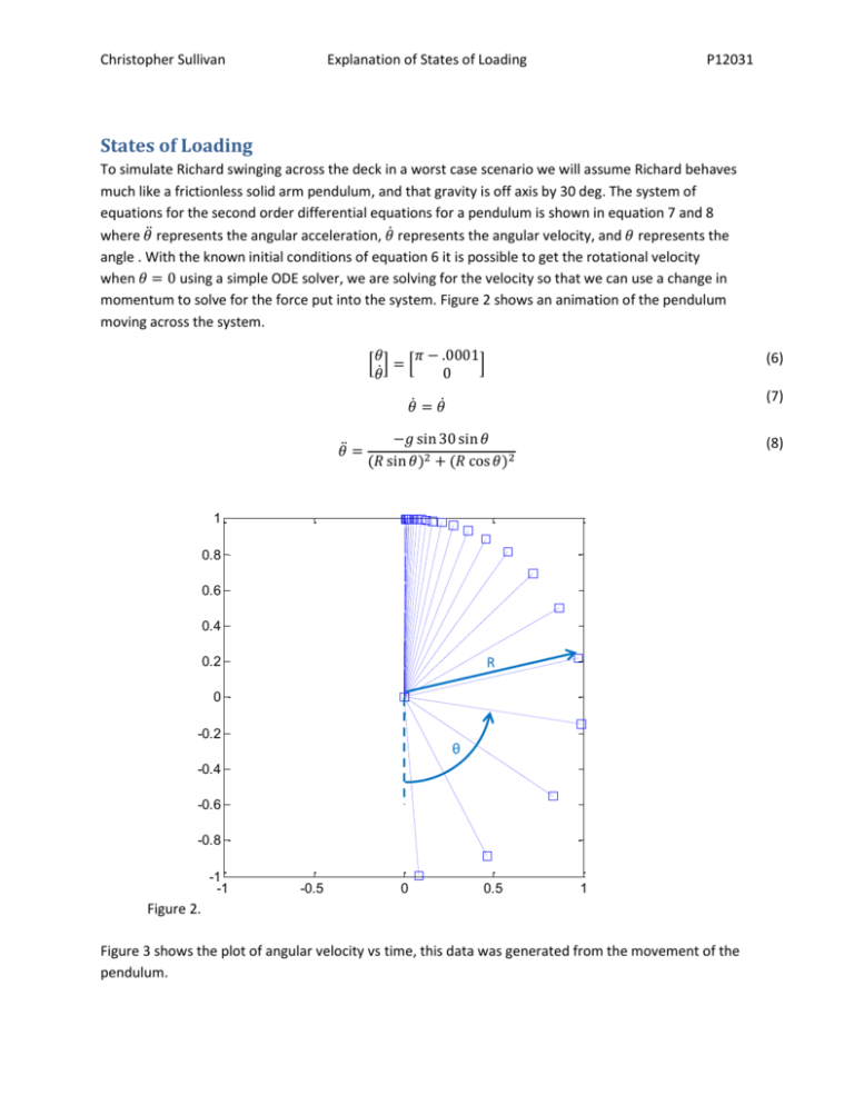
Christopher Sullivan Explanation of States of Loading P12031 States of Loading To simulate Richard swinging across the deck in a worst case scenario we will assume Richard behaves much like a frictionless solid arm pendulum, and that gravity is off axis by 30 deg. The system of equations for the second order differential equations for a pendulum is shown in equation 7 and 8 where 𝜃̈ represents the angular acceleration, 𝜃̇ represents the angular velocity, and 𝜃 represents the angle . With the known initial conditions of equation 6 it is possible to get the rotational velocity when 𝜃 = 0 using a simple ODE solver, we are solving for the velocity so that we can use a change in momentum to solve for the force put into the system. Figure 2 shows an animation of the pendulum moving across the system. 𝜃̈ = 𝜃 𝜋 − .0001 [ ̇] = [ ] 0 𝜃 (6) 𝜃̇ = 𝜃̇ (7) −𝑔 sin 30 sin 𝜃 (𝑅 sin 𝜃)2 + (𝑅 cos 𝜃)2 (8) 1 0.8 0.6 0.4 R 0.2 0 -0.2 θ -0.4 -0.6 -0.8 -1 -1 -0.5 0 0.5 1 Figure 2. Figure 3 shows the plot of angular velocity vs time, this data was generated from the movement of the pendulum. Christopher Sullivan Explanation of States of Loading P12031 Angular Velocity vs Time 0 Angular Velocity (rad/s) -1 -2 -3 -4 -5 -6 1 1.5 2 2.5 3 3.5 Time (s) Figure 3. As you can see the maximum angular velocity that will be reached is at the vertex of the swing and is 5.4 𝑟𝑎𝑑⁄𝑠 converting this can be converted to meters per second and mph respectively by multiply by the radius of the track. 𝑣𝑅 = 3.7 𝑚⁄𝑠 (9) 𝑣𝑅 = −8.2 𝑚𝑝ℎ (10) Once we know the velocity that Richard will be traveling when he hits the track stop we can by using conservation of energy. The impact force felt by the track stopper will be the difference in kinetic energy divided by the distance after the collision that it took Richard to come to rest. To make it easier we are assuming that Richard bounces back about 5 in or .127 m. Using equation 9 where 𝑣𝑟 is the velocity of Richard, 𝑚 is the mass of Richard and the chair, and 𝑑 will be the linear distance Richard bounces back off the rubber. 1 2 𝑣𝑟 𝑚⁄ 𝐹𝑐 = 2 𝑑 The force of the impact is roughly equivalent to 6000N or 1348 lb. This force will later be applied to the model of our track platform. (11) Christopher Sullivan Explanation of States of Loading P12031 To account for the adverse weather condition that Richard will be facing on the boat some initial background about waves needs to be gathered first so that we might make some basic assumptions. The first basic assumption is defining a “bad” wave, essentially the sizing of the waves that Richard might face. Based on figure 4 an average height of 7m with sustained winds of 40knots and also from figure 4 a period of 16 seconds will be assumed to be a worst case scenario. From figure 5 the wavelength of a wave with a period of 16 sec is known to be about 400m now that relative to the boat is quite long and therefore the boat will generally follow the angle of the wave as it floats long its surface. Now that we have a handle on the height, and speed of these waves, we can start to calculate the significant accelerations that our system needs to be able to handle. Acceleration of Richard will also cause a significant internal reaction forces between Richard, his chair, and the track platform. Figure 4. (Anthoni, 2000) Figure 5. (Anthoni, 2000) Christopher Sullivan Explanation of States of Loading P12031 To calculate these accelerations a wave path must be created, that can be written as a simple mathematical equation. Assuming the wave is in the shape of a sin wave the equation of the wave can be show as equation 10. Where Ymax is the maximum height of the wave and P is the period of the waves. Figure 6 shows the high of the wave as a function of time. 𝑌𝑤 (𝑡) = 𝑦𝑚𝑎𝑥 2𝜋𝑡 𝜋 𝑦𝑚𝑎𝑥 sin ( − )+ 2 𝑃 2 2 7 Wave 6 5 Hight 4 3 2 1 0 0 Figure 6. 2 4 6 8 Time (s) 10 12 14 16 Because Richard is not in the dead center of the boat and because the boat generally follows the angle of the wave as it travels along its surface there will be relative motion. To find this the first thing we will do is find the angle that the boat is at and how this changes with time. To do this we take the equation 9 and differentiate it. Now you have an equation that represent the slope of the boat with respect to time, and to get it into a usable angle you simply need to take the arctangent of the slope. Figure 7 represents the set of angles that the boat will be at with respect to time while the wave moves under it. Christopher Sullivan Explanation of States of Loading P12031 1 Angle Of the Boat 0.8 0.6 Angle (rad) 0.4 0.2 0 -0.2 -0.4 -0.6 -0.8 -1 0 2 4 6 Figure 7. 8 Time (s) 10 12 14 16 Now that we have the angle we can use it to calculate the position of Richard with respect to the center of the boat. With this in mind you can differentiate these equations twice to get the acceleration of Richard, and the system. The resulting Accelerations are shown in figure 8. 0.8 Acc Y Acc X 0.6 Acceleration (m/s 2) 0.4 0.2 0 -0.2 -0.4 -0.6 -0.8 0 Figure 8. 2 4 6 8 Time (s) 10 12 14 16 Christopher Sullivan Explanation of States of Loading P12031 As you can see there is a spike in the acceleration in the X direction right as the boat would be rounding the top of the wave which is exactly what we expected to see. Now that we have this information we will be able to calculate the body forces of the individual pieces along with the reactions that they may cause to their interlocking parts. Assuming Richard and his chair weigh approximately 136kg using simple force = mass*acceleration and adding in gravitational effects. At their peak acceleration he is applying 1425 newtons down on the track, and 24 newtons towards the middle of the boat. This information can be fed into an ANSYS model of the track platform to find the stress distribution of the platform. Christopher Sullivan Explanation of States of Loading P12031 To simulate a crash with another boat there are just too many variables to take into consideration. So instead of finding out exactly how much acceleration there is in a single kind of crash table 1 lists out the magnitude of different kinds of common acceleration. Table 1. (http://en.wikipedia.org/wiki/G-force) For our experiments with ANSYS we will slowly ramp up the acceleration until the maximum Von Mises Stress exceeds these percussionary limits (at around 1 FOS) and this will be the amount of acceleration that the system will be rated to handle. There will be five cases all include Richards internal forces added to the situation at the unsupported area of the track, pure port acceleration, a pure stern acceleration, pure bow acceleration, an equal combination of port and bow, and port and stern. Once we know these maximum accelerations in each direction it can be converted to Gs to compare with other kinds of high G activities. Christopher Sullivan Explanation of States of Loading P12031 Works Cited Anthoni, D. J. (2000). Oceanography: waves theory and principles of waves, how they work and what causes them. Retrieved 10 27, 2011, from seafriends: http://www.seafriends.org.nz/oceano/waves.htm MatWeb. (n.d.). Retrieved 11 3, 2011, from Aluminum 2011-T6: http://www.matweb.com/search/DataSheet.aspx?MatGUID=66a81429bea54053bbdc39cfce0f2 407&ckck=1 The Engineering ToolBox. (n.d.). Retrieved 11 3, 2011, from Modulus or Rigidity: http://www.engineeringtoolbox.com/modulus-rigidity-d_946.html
