Amejka – Rolston Senior IDS Using SolidWorks in Calculus
advertisement

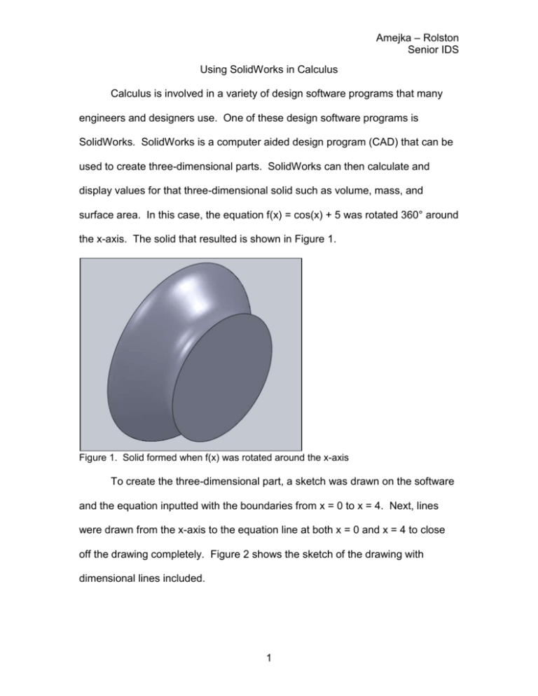
Amejka – Rolston Senior IDS Using SolidWorks in Calculus Calculus is involved in a variety of design software programs that many engineers and designers use. One of these design software programs is SolidWorks. SolidWorks is a computer aided design program (CAD) that can be used to create three-dimensional parts. SolidWorks can then calculate and display values for that three-dimensional solid such as volume, mass, and surface area. In this case, the equation f(x) = cos(x) + 5 was rotated 360° around the x-axis. The solid that resulted is shown in Figure 1. Figure 1. Solid formed when f(x) was rotated around the x-axis To create the three-dimensional part, a sketch was drawn on the software and the equation inputted with the boundaries from x = 0 to x = 4. Next, lines were drawn from the x-axis to the equation line at both x = 0 and x = 4 to close off the drawing completely. Figure 2 shows the sketch of the drawing with dimensional lines included. 1 Amejka – Rolston Senior IDS Figure 2. Closed-off sketch of f(x) from x = 0 to x = 4 Once the sketch was fully closed off, the part was rotated around the xaxis to create a three-dimensional solid. Figure 3 shows the drawing of the part with the Top and Isometric views on the top row and the Front and Right views on the bottom row. Figure 3. Drawing of the part with four different views The end goal was to verify that the SolidWorks method of volume calculation and the calculus method of volume calculation produced the same 2 Amejka – Rolston Senior IDS results. The volume was calculated using SolidWorks after the threedimensional part was created. SolidWorks determined the volume to be 297.46 cubic inches, which is highlighted in a box in Figure 4. Figure 4. Screen shot of the mass properties window Calculus was used to confirm the value that SolidWorks calculated for the volume. The calculus topic is known as solids of revolution. The method used was the disk method, because when the solid is cut into small cross-sections, the small cross-sections are disks. Figures 5, 6, and 7 show the solid cut into various disk cross-sections at various spots. Figure 5. Large cross-section Figure 6. Small cross-section 3 Figure 7. Medium cross-section Amejka – Rolston Senior IDS The disk method uses the equation πr2, where r is the radius (in this case this is the y-value). This and the antiderivative are shown in figure 8. The antiderivative was found using the even function rules for integration. 4 4 1. ∫0 𝜋𝑟 2 𝑑𝑟 =∫0 𝜋𝑦 2 𝑑𝑦 4 ∫0 𝜋(cos(𝑥) + 5)2 𝑑𝑥 1 2. 𝜋(cos(𝑥)2 + 10 cos(𝑥) + 25)=𝜋(4 sin(2𝑥) + 10 sin(𝑥) + 25.5𝑥) Figure 8. Integration of f(x) The integrand was integrated from 0 to 4, since those were the boundaries used to sketch the solid. The Fundamental Theorem of Calculus states that 𝑏 ∫𝑎 𝑓(𝑥) = 𝐹(𝑏) − 𝐹(𝑎) where F is the antiderivative of f(x). For this case, we’d use 4 as b and 0 as a. The steps of integration and the calculations are shown in figure 9. When 4 is plugged in for x: 1 𝜋( sin(2(4)) + 10 sin(4) + 25.5(4))=297.444 4 When 0 is plugged in for x: 1 𝜋(4 sin(2(0)) + 10 sin(0) + 25.5(0))=0 So, 297.444 – 0 = 297.444 Figure 9. Steps of integration and the final volume The volume that was calculated using SolidWorks was 297.46 cubic inches, and the volume that was calculated by hand using the disk method and integration was 297.444 cubic inches. There is virtually no variation between the two values and virtually no percent error. 4


