ASSIGNMENT MEELC303 1 A 1500 nF capacitor is connected in
advertisement
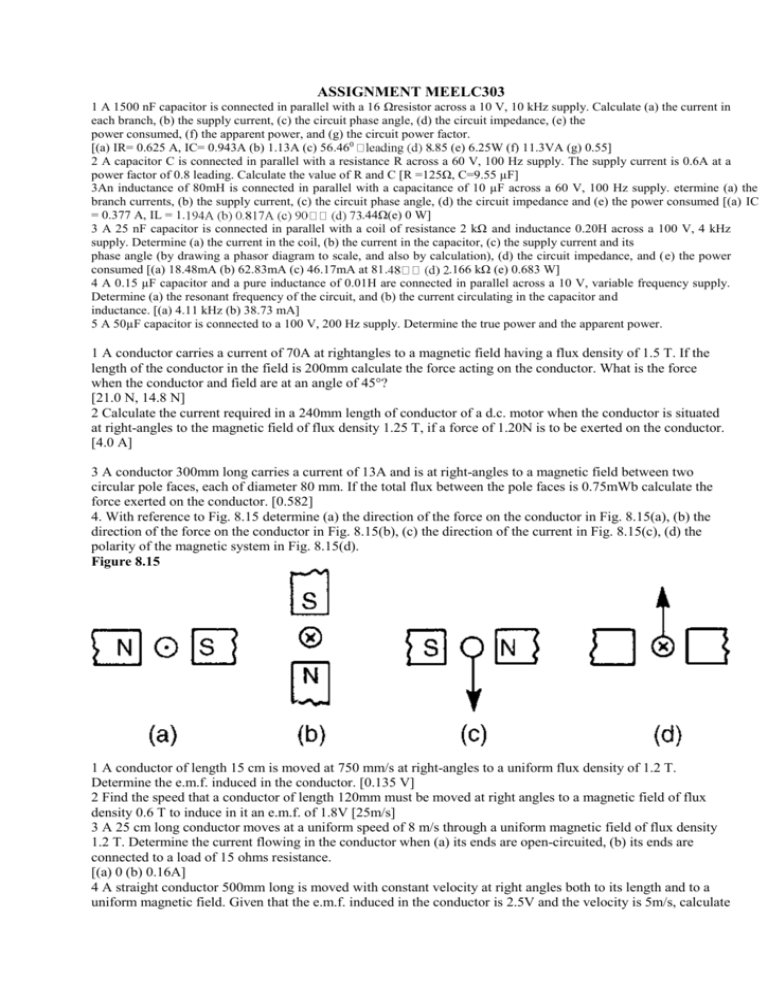
ASSIGNMENT MEELC303 1 A 1500 nF capacitor is connected in parallel with a 16 Ωresistor across a 10 V, 10 kHz supply. Calculate (a) the current in each branch, (b) the supply current, (c) the circuit phase angle, (d) the circuit impedance, (e) the power consumed, (f) the apparent power, and (g) the circuit power factor. [(a) IR= 0.625 A, IC= 0.943A (b) 1.13A (c) 56.460 .85 (e) 6.25W (f) 11.3VA (g) 0.55] 2 A capacitor C is connected in parallel with a resistance R across a 60 V, 100 Hz supply. The supply current is 0.6A at a power factor of 0.8 leading. Calculate the value of R and C [R =125Ω, C=9.55 µF] 3An inductance of 80mH is connected in parallel with a capacitance of 10 µF across a 60 V, 100 Hz supply. etermine (a) the branch currents, (b) the supply current, (c) the circuit phase angle, (d) the circuit impedance and (e) the power consumed [(a) IC = 0.377 A, IL = 1. .44Ω(e) 0 W] 3 A 25 nF capacitor is connected in parallel with a coil of resistance 2 kΩ and inductance 0.20H across a 100 V, 4 kHz supply. Determine (a) the current in the coil, (b) the current in the capacitor, (c) the supply current and its phase angle (by drawing a phasor diagram to scale, and also by calculation), (d) the circuit impedance, and (e) the power consumed [(a) 18.48mA (b) 62.83mA (c) 46.17mA at 81. .166 kΩ (e) 0.683 W] 4 A 0.15 µF capacitor and a pure inductance of 0.01H are connected in parallel across a 10 V, variable frequency supply. Determine (a) the resonant frequency of the circuit, and (b) the current circulating in the capacitor and inductance. [(a) 4.11 kHz (b) 38.73 mA] 5 A 50µF capacitor is connected to a 100 V, 200 Hz supply. Determine the true power and the apparent power. 1 A conductor carries a current of 70A at rightangles to a magnetic field having a flux density of 1.5 T. If the length of the conductor in the field is 200mm calculate the force acting on the conductor. What is the force when the conductor and field are at an angle of 45°? [21.0 N, 14.8 N] 2 Calculate the current required in a 240mm length of conductor of a d.c. motor when the conductor is situated at right-angles to the magnetic field of flux density 1.25 T, if a force of 1.20N is to be exerted on the conductor. [4.0 A] 3 A conductor 300mm long carries a current of 13A and is at right-angles to a magnetic field between two circular pole faces, each of diameter 80 mm. If the total flux between the pole faces is 0.75mWb calculate the force exerted on the conductor. [0.582] 4. With reference to Fig. 8.15 determine (a) the direction of the force on the conductor in Fig. 8.15(a), (b) the direction of the force on the conductor in Fig. 8.15(b), (c) the direction of the current in Fig. 8.15(c), (d) the polarity of the magnetic system in Fig. 8.15(d). Figure 8.15 1 A conductor of length 15 cm is moved at 750 mm/s at right-angles to a uniform flux density of 1.2 T. Determine the e.m.f. induced in the conductor. [0.135 V] 2 Find the speed that a conductor of length 120mm must be moved at right angles to a magnetic field of flux density 0.6 T to induce in it an e.m.f. of 1.8V [25m/s] 3 A 25 cm long conductor moves at a uniform speed of 8 m/s through a uniform magnetic field of flux density 1.2 T. Determine the current flowing in the conductor when (a) its ends are open-circuited, (b) its ends are connected to a load of 15 ohms resistance. [(a) 0 (b) 0.16A] 4 A straight conductor 500mm long is moved with constant velocity at right angles both to its length and to a uniform magnetic field. Given that the e.m.f. induced in the conductor is 2.5V and the velocity is 5m/s, calculate the flux density of the magnetic field. If the conductor forms part of a closed circuit of total resistance 5 ohms, calculate the force on the conductor. [1 T, 0.25 N] 1 Find the e.m.f. induced in a coil of 200 turns when there is a change of flux of 30mWb linking with it in 40 ms. [_150 V] 2 An e.m.f. of 25V is induced in a coil of 300 turns when the flux linking with it changes by 12 mWb. Find the time, in milliseconds, in which the flux makes the change. [144 ms] 3 An ignition coil having 10 000 turns has an e.m.f. of 8 kV induced in it. What rate of change of flux is equired for this to happen? [0.8 Wb/s] 4 A flux of 0.35mWb passing through a 125-turn coil is reversed in 25 ms. Find the magnitude of the average e.m.f. induced. [3.5 V] 5 Calculate the e.m.f. induced in a coil of inductance 6H by a current changing at a rate of 15 A/s [_90 V] 1 A flux of 30mWb links with a 1200 turn coil when a current of 5A is passing through the coil. Calculate (a) the inductance of the coil, (b) the energy stored in the magnetic field, and (c) the average e.m.f. induced if the current is reduced to zero in 0.20 s [(a) 7.2H (b) 90 J (c) 180 V] 2 An e.m.f. of 2 kV is induced in a coil when a current of 5A collapses uniformly to zero in 10 ms. Determine the inductance of the coil. [4 H] 3 An average e.m.f. of 60V is induced in a coil of inductance 160mH when a current of 7.5A is reversed. alculate the time taken for the current to reverse. [40ms] 4 A coil of 2500 turns has a flux of 10mWb linking with it when carrying a current of 2A Calculate the coil inductance and the e.m.f. induced in the coil when the current collapses to zero in 20 ms. [12.5H, 1.25 kV] 1 A transformer has 600 primary turns connected to a 1.5 kV supply. Determine the number of secondary turns for a 240V output voltage, assuming no losses. [96] 2 An ideal transformer with a turns ratio of 2:9 is fed from a 220V supply. Determine its output voltage. [990 V] 3 A transformer has 800 primary turns and 2000 secondary turns. If the primary voltage is 160 V, determine the secondary voltage assuming an ideal transformer. [400 V] 4 An ideal transformer with a turns ratio of 3:8 is fed from a 240V supply. Determine its output voltage. [640 V] 5 An ideal transformer has a turns ratio of 12:1 and is supplied at 192 V. Calculate the secondary voltage. [16V] 6 A transformer primary winding connected across a 415V supply has 750 turns. Determine how many turns must be wound on the secondary side if an output of 1.66 kV is required. [3000 turns] 7 An ideal transformer has a turns ratio of 12:1 and is supplied at 180V when the primary current is 4 A. Calculate the secondary voltage and current. [15 V, 48 A] 8 A step-down transformer having a turns ratio of 20:1 has a primary voltage of 4 kV and a load of 10 kW. Neglecting losses, calculate the value of the secondary current. [50 A] 9 A transformer has a primary to secondary turns ratio of 1:15. Calculate the primary voltage necessary to supply a 240V load. If the load current is 3A determine the primary current. Neglect any losses. [16 V, 45 A] 10 A 10 kVA, single-phase transformer has a turns ratio of 12:1 and is supplied from a 2.4 kV supply. Neglecting losses, determine (a) the full load secondary current, (b) the minimum value of load resistance which can be connected across the secondary winding without the kVA rating being exceeded, and (c) the primary current. [(a) 50A (b) 4Ω (c) 4.17A] 11 A 20Ω resistance is connected across the secondary winding of a single-phase power transformer whose secondary voltage is 150 V. Calculate the primary voltage and the turns ratio if the supply current is 5A, neglecting losses. [225 V, 3:2] 1 A 60 kVA, 1600 V/100 V, 50 Hz, single-phase transformer has 50 secondary windings. Calculate (a) the primary and secondary current, (b) the number of primary turns, and (c) the maximum value of the flux [(a) 37.5 A, 600A (b) 800 (c) 9.0 mWb] 2 A single-phase, 50 Hz transformer has 40 primary turns and 520 secondary turns. The cross-sectional area of the core is 270 cm2. When the primary winding is connected to a 300 volt supply, determine (a) the maximum value of flux density in the core, and (b) the voltage induced in the secondary winding [(a) 1.25 T (b) 3.90 kV] 3 A single-phase 800 V/100 V, 50 Hz transformer has a maximum core flux density of 1.294 T and an effective cross-sectional area of 60 cm2. Calculate the number of turns on the primary and secondary windings. [464, 58] 4 A 3.3 kV/110 V, 50 Hz, single-phase transformer is to have an approximate e.m.f. per turn of 22V and operate with a maximum flux of 1.25 T. Calculate (a) the number of primary and secondary turns, and (b) the rosssectional area of the core [(a) 150, 5 (b) 792.8 cm2] 1 A single-phase transformer has a voltage ratio of 6:1 and the h.v. winding is supplied at 540 V. The secondary winding provides a full load current of 30A at a power factor of 0.8 lagging. Neglecting losses, find (a) the rating of the transformer, (b) the power supplied to the load, (c) the primary current [(a) 2.7 kVA (b) 2.16kW (c) 5 A] 2 A single-phase transformer is rated at 40 kVA The transformer has full-load copper losses of 800W and iron losses of 500 W. Determine the transformer efficiency at full load and 0.8 power factor [96.10%] 3 Determine the efficiency of the transformer in problem 2 at half full-load and 0.8 power factor [95.81%] 4 A 100 kVA, 2000 V/400 V, 50 Hz, single-phase transformer has an iron loss of 600W and a full-load copper loss of 1600 W. Calculate its efficiency for a load of 60 kW at 0.8 power factor. [97.56%] 5 Determine the efficiency of a 15 kVA transformer for the following conditions: (i) full-load, unity power factor (ii) 0.8 full-load, unity power factor (iii) half full-load, 0.8 power factor Assume that iron losses are 200Wand the fullload copper loss is 300W [(a) 96.77% (ii) 96.84% (iii) 95.62%] 1 A three-phase transformer has 600 primary turns and 150 secondary turns. If the supply voltage is 1.5 kV determine the secondary line voltage on no-load when the windings are connected (a) delta-star (b) star-delta [(a) 649.5V (b) 216.5 V] 1 A 4-pole, wave-connected armature of a d.c. machine has 750 conductors and is driven at 720 rev/min. If the useful flux per pole is 15 mWb, determine the generated e.m.f. [270 volts] 2 A 6-pole generator has a lap-wound armature with 40 slots with 20 conductors per slot. The flux per pole is 25mWb. Calculate the speed at which the machine must be driven to generate an e.m.f. of 300V [15 rev/s or 900 rev/min] 3 A 4-pole d.c. motor has a wave-wound armature with 800 conductors. The useful flux per pole is 20mWb. Calculate the torque exerted when a current of 40A flows in each armature conductor. [203.7Nm] 4 Calculate the torque developed by a 240V d.c. motor whose armature current is 50 A, armature resistance is 0.6Ω and is running at 10 rev/s [167.1Nm] 5 An 8-pole lap-wound d.c. motor has a 200V supply. The armature has 800 conductors and a resistance of 0.8Ω. If the useful flux per pole is 40mWb and the armature current is 30 A, calculate (a) the speed and (b) the torque developed [(a) 5.5 rev/s or 330 rev/min (b) 152.8 Nm 1 The synchronous speed of a 3-phase, 4-pole induction motor is 60 rev/s. Determine the frequency of the supply to the stator windings. [120 Hz] 2 The synchronous speed of a 3-phase induction motor is 25 rev/s and the frequency of the supply to the stator is 50 Hz. Calculate the equivalent number of pairs of poles of the motor. [2] 3 A 6-pole, 3-phase induction motor is connected to a 300 Hz supply. Determine the speed of rotation of the magnetic field produced by the stator. [100 rev/s]
