International Journal of Science, Engineering and Technology Research (IJSETR)
Volume 1, Issue 1, July 2012
Basic Concepts of Doubly Fed Induction
Generator Driven by Wind Energy
Conversion System
Shwe Hlaing
Abstract— With increased production capacity in wind farms,
their role in power system stability has become important. The
inertia response of a generator is influenced by the sensitivity of
the generator’s electromagnetic torque to changes in the power
system frequency. DFIG has low inertia response. Inertia
response of DFIG can be improved by adding feedback
parameter as a function of the rate of the change of the grid
frequency to reference electromagnetic torque. At any mode of
operation, rotational speed of the turbine must be changed and
thus active and reactive power of the generator must be
changed.
improving the efficiency.
II. WIND ENERGY CONVERSION SYSTEM
The development in wind turbine systems has been steady
for the last 25 years and four to five generation of wind
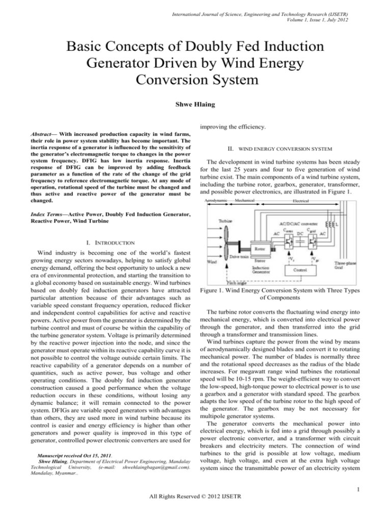
turbine exist. The main components of a wind turbine system,
including the turbine rotor, gearbox, generator, transformer,
and possible power electronics, are illustrated in Figure 1.
Aerodynamic
Mechanical
Electrical
Index Terms—Active Power, Doubly Fed Induction Generator,
Reactive Power, Wind Turbine
I. INTRODUCTION
Wind industry is becoming one of the world’s fastest
growing energy sectors nowadays, helping to satisfy global
energy demand, offering the best opportunity to unlock a new
era of environmental protection, and starting the transition to
a global economy based on sustainable energy. Wind turbines
based on doubly fed induction generators have attracted
particular attention because of their advantages such as
variable speed constant frequency operation, reduced flicker
and independent control capabilities for active and reactive
powers. Active power from the generator is determined by the
turbine control and must of course be within the capability of
the turbine generator system. Voltage is primarily determined
by the reactive power injection into the node, and since the
generator must operate within its reactive capability curve it is
not possible to control the voltage outside certain limits. The
reactive capability of a generator depends on a number of
quantities, such as active power, bus voltage and other
operating conditions. The doubly fed induction generator
construction caused a good performance when the voltage
reduction occurs in these conditions, without losing any
dynamic balance; it will remain connected to the power
system. DFIGs are variable speed generators with advantages
than others, they are used more in wind turbine because its
control is easier and energy efficiency is higher than other
generators and power quality is improved in this type of
generator, controlled power electronic converters are used for
Manuscript received Oct 15, 2011.
Shwe Hlaing, Department of Electrical Power Engineering, Mandalay
Technological University, (e-mail: shwehlaingbagan@gmail.com).
Mandalay, Myanmar..
Figure 1. Wind Energy Conversion System with Three Types
of Components
The turbine rotor converts the fluctuating wind energy into
mechanical energy, which is converted into electrical power
through the generator, and then transferred into the grid
through a transformer and transmission lines.
Wind turbines capture the power from the wind by means
of aerodynamically designed blades and convert it to rotating
mechanical power. The number of blades is normally three
and the rotational speed decreases as the radius of the blade
increases. For megawatt range wind turbines the rotational
speed will be 10-15 rpm. The weight-efficient way to convert
the low-speed, high-torque power to electrical power is to use
a gearbox and a generator with standard speed. The gearbox
adapts the low speed of the turbine rotor to the high speed of
the generator. The gearbox may be not necessary for
multipole generator systems.
The generator converts the mechanical power into
electrical energy, which is fed into a grid through possibly a
power electronic converter, and a transformer with circuit
breakers and electricity meters. The connection of wind
turbines to the grid is possible at low voltage, medium
voltage, high voltage, and even at the extra high voltage
system since the transmittable power of an electricity system
1
All Rights Reserved © 2012 IJSETR
International Journal of Science, Engineering and Technology Research (IJSETR)
Volume 1, Issue 1, July 2012
usually increases with increasing the voltage level. While
most of the turbines are nowadays connected to the medium
voltage system, large offshore wind farms are connected to
the high and extra high voltage level.
III. GENERATOR SYSTEMS FOR WIND TURBINES
Both induction and synchronous generators can be used for
wind turbine systems. Induction generators can be used in a
fixed-speed system or a variable-speed system, while
synchronous generators are normally used in power electronic
interfaced variable-speed systems. Mainly, three types of
induction generators are used in wind power conversion
systems: cage rotor, wound rotor with slip control by
changing rotor resistance, and doubly fed induction
generators. The cage rotor induction machine can be directly
connected into an ac system and operates at a fixed speed or
uses a full-rated power electronic system to operate at
variable speed. The wound rotor generator with
rotor-resistance-slip control is normally directly connected to
an ac system, but the slip control provides the ability of
changing the operation speed in a certain range. The doubly
fed induction generators provide a wide range of speed
variation depending on the size of power electronic converter
systems. In this paper we first discuss the systems without
power electronics except the thyristor soft starter, and then
discuss the variable-speed wind turbine systems, including
those with partially rated power electronics and the full-scale
power electronic interfaced wind turbine systems.
A. Fixed-speed Wind Turbines
In fixed-speed wind turbines, the generator is directly
connected to the mains supply grid. The frequency of the grid
determines the rotational speed of the generator and thus of
the rotor. The generator speed depends on the number of pole
pairs and the frequency of the grid. The basic configurations
of three different fixed speed concepts are shown in Figure 2.
The advantage of wind turbines with induction generators is
the simple and cheap construction. In addition, no
synchronization device is required.
Figure 2. Wind turbine systems without power converter, but
with aerodynamic power control.(a) Pitch controlled (System
I), (b) stall controlled (System II), and (c) active stall
controlled (System III).
B. Variable Speed Wind Turbines
In variable-speed systems the generator is normally
connected to the grid by a power electronic system. For
synchronous generators and for induction generators without
rotor windings, a full-rated power electronic system is
connected between the stator of the generator and the grid,
where the total power production must be fed through the
power electronic system. For induction generators with rotor
windings, the stator of the generator is connected to the grid
directly. Only the rotor of the generator is connected through
a power electronic system. This gives the advantage that only
a part of the power production is fed through the power
electronic converter. This means the nominal power of the
converter system can be less than the nominal power of the
wind turbine. In general the nominal power of the converter
may be 30% of the power rating of the wind turbine, enabling
a rotor speed variation in the range of 30% of the nominal
speed. By controlling the active power of the converter, it is
possible to vary the rotational speed of the generator and thus
of the rotor of the wind turbines. The generator for wind
turbine systems shown in Figure 3 is an induction generator
with a wounded rotor.
Figure 3. Wind turbine topologies with partially rated power
electronics and limited speed range. Rotor-resistance
converter (System IV) and doubly-fed induction generator
(System V).
2
All Rights Reserved © 2012 IJSETR
International Journal of Science, Engineering and Technology Research (IJSETR)
Volume 1, Issue 1, July 2012
IV. DOUBLY FED INDUCTION GENERATOR
Doubly-fed electric machines are basically electric
machines that are fed ac currents into both the stator and the
rotor windings. Most doubly-fed electric machines in industry
today are three-phase wound-rotor induction machines.
Although their principles of operation have been known for
decades, doubly-fed electric machines have only recently
entered into common use. This is due almost exclusively to
the advent of wind power technologies for electricity
generation. The primary advantage of doubly-fed induction
generators when used in wind turbines is that they allow the
amplitude and frequency of their output voltages to be
maintained at a constant value, no matter the speed of the
wind blowing on the wind turbine rotor. Because of this,
doubly-fed induction generators can be directly connected to
the ac power network and remain synchronized at all times
with the ac power network. Other advantages include the
ability to control the power factor, while keeping the power
electronics devices in the wind turbine at a moderate size. A
more detailed picture of the DFIG system with a back-to-back
converter can be seen in Figure 4. The back-to-back converter
consists of two converters, i.e., machine-side converter and
grid-side converter that are connected back-to-back. Between
the two converters a dc-link capacitor is placed, as energy
storage, in order to keep the voltage variations (or ripple) in
the dc-link. With the machine-side converter it is possible to
control the torque or the speed of the DFIG and also the power
factor at the stator terminals, while the main objective for the
grid-side converter is to keep the dc-link voltage constant.
thus, the torque is negative during generating operation. So,
basic concepts of slip and frequency is yields:
ωs ω m
ωs
n nm
= s
ns
Slip = s
ns
60f s
rpm
p
nm = ns (1-s)
ωm = ωs (1-s)
The induced rotor voltages have frequency of :
ωr = ωs -ωm
ωr
ωs
s
ωr = sωs
fr = sfs
where,
ns = synchronous speed of machines
fs = stator frequency or supply frequency
p = number of pole pairs
Synchronous speed induces an emf in the rotor windings
according to:
eind = ( v B) . L
where,
eind = induced emf in one conductor of rotor
v = velocity of conductor relative to stator flux rotation
B = stator magnetic flux density vector
L = length of conductor
VI. POWER AND TORQUE EXPRESSION OF DFIG
Figure 4. DFIG system with a back-to-back converter
V. OPERATING PRINCIPLE OF WOUND-ROTOR INDUCTION
MACHINE
A wound-rotor induction machine can be operated as a
doubly-fed induction machine (DFIM) when a power
converter is present in its rotor circuit. This converter directs
the power flow into and out of the rotor windings. Because the
DFIM can operate as either a motor or a generator at
sub-synchronous and super-synchronous speeds. When the
machine runs above synchronous speed, this operation is
termed super-synchronous operation. Similarly, operation
below synchronous speed is called sub-synchronous
operation. In both sub- and super-synchronous operation, the
machine can be operated either as a motor or a generator. In
the motoring mode of operation, the torque produced by the
machine is positive. On the other hand, during generating
operation, the machine needs mechanical torque as input;
Power balance relation:
Pmech = Ps + Pr – Ploss,s – Ploss,r
where,
Ps and Pr are powers entering the machine through stator
and rotor windings
Ploss,s and Ploss,r are the stator and rotor winding losses
Pmech =
3 I r (R eq ) 3ReV eq I r *
2
1 s
2 R (1 s)
3 Ir r
3Re V r
I r *
s
s
1 s
2 R (1 s)
= 3 Ir s
3
ReV r I r *
s
s
=
Since,
Pmech = TemΩm
= Tem
ωm
p
3
All Rights Reserved © 2012 IJSETR
International Journal of Science, Engineering and Technology Research (IJSETR)
Volume 1, Issue 1, July 2012
Tem = Pmech
=3
Tem =
p
ωm
1 s
p 2 R r (1 s)
p
Ir
Re V r
3
I r *
ωm
s
ωm s
3
p 2 R r ωm
p
3
I r
ωm
ωm
ωr
2
=
3p I r R r
ωr
ωm
ReV r I r *
ω
r
VIII. CONCLUSION
3p
ReV r I r *
ωr
3p
Vr I r cos( v i )
ωr
2
=
3p I r R r
ωr
VII. CHARACTERISTIC OF DFIG IN SIMULINK
The characteristics of DFIG model is shown in Figure 5 and
Figure 6.
Wind Turbine Characteristics (w = 1.2 pu, pitch angle increases by step of 2 deg.)
1.5
P (pu)
shown in Figure 5, Lambda value is decreased as the wind
speed increased. The last axis is displayed the Power
Coefficient (Cp) versus wind speed. In this axis, the power
coefficient is expressed for various pitch angle as in first axis.
Since the designed rated wind speed of built in DFIG is 11
m/s, the power coefficient is maximum at this wind speed.
Figure 6. is illustrated the detail characteristics of power
coefficient versus wind speed.
Various wind turbine systems with different generators and
power electronic converters have been described. Different
types of wind turbine systems will have quite different
performances and controllability, which was discussed with
some results from study examples. The wind farms with
different turbines may need different configurations for best
use of the technical merits; therefore, electrical topologies of
wind farms with different wind turbines have been briefed. In
general, the connection of DFIG improve the stability of the
system and the load voltage. Wind power generation with
DFIG provides better performance for terminal voltage
recovery after the load connects suddenly.
1
ACKNOWLEDGMENT
0.5
0
0
5
10
15
20
25
30
35
0
5
10
15
20
25
30
35
20
Lambda
15
10
5
0
0.6
The author wishes to express her deepest gratitude to her
teachers, Department of Electrical Power Engineering,
Mandalay Technological University. The author also wishes
to extend special thanks to her parent, her friends for their
supports and help. Similar thanks to all for their instructions
and willingness to share their ideas throughout all those years
of study.
0.5
Cp
0.4
REFERENCES
0.3
0.2
0.1
0
0
5
10
15
20
25
30
35
Wind Speed (m/s)
Figure 5. Characteristics of DFIG
Figure 6. Detail Characteristics of Power Coefficient versus
Wind Speed
Goldind. E.W, “The Generation of Electricity by Wind Power”, E &
F.N Spon Limited, 22 Henrietta Street, London. 1995.
[2] E. Muljadi, C.P. “Wind Farm Power System Model Development,”
World Renewable Energy Congress VIII, Colorado, Butterfield. 2004.
[3] K. Johnsen, B. Eliasson, “SIMULINK Implementation of Wind Farm
Model for use in Power System Studies,” Nordic Wind Power
Conference, Chalmers University of Technology,2004.
[4] LEONHARD, W. “Control of electrical drives”Springer-Verlag, 1985.
[5] JONES, S.R., and JONES, R.“Control strategy for
Sinusoidal
supply side converters”, IEEColloquium on Developments in real
timeControl for induction motor drives. Digest 1993/024, February
1993.
[6] CARDICI, I., and ERMIS, M.,“Double-outputInduction generator
operating at sub synchronous andsuper synchronous speed:steady
statePerformance optimization and wind energy
recovery”,IEE
proc. B, 1992, 139, (5), pp.429- 442
[7] MITSUTOSHI, Y., and MOTOYOSHI, O., “Active and reactive power
control for doubly fed wound rotor induction generator”, IEE Trans.
Power Electron, 6, (4), pp. 624-629,1991.
[8] R .Erickson. Fundamentals of PowerElectronics. Kluwer, 1997.
Shwe Hlaing received her B.E (Electrical power) degree from
Technological University, in 2009 and now pursuing M.E (Electrical Power)
at Mandalay Technological University.
[1]
There are three axes in Figure 5. The first axis illustrates
the power output in per unit versus wind speed in meter per
second. Since the cut in wind speed is 5 m/s and cut out wind
speed is 30 m/s, the curves are drawn for power versus wind
speed with pitch angle increased by step of two degree. The
second axis is described Lambda versus wind speed. As
4
All Rights Reserved © 2012 IJSETR


