Please select a proper .LSB file from below dialog box.
advertisement
Introduction to Advantech 32-bit LabVIEW Driver V1.xx for
Windows NT and Windows 95
How to Install/Uninstall Advantech 32-bit LabVIEW driver
Install Advantech 32-bit LabVIEW driver
There are totally 4 disks for the Advantech 32-bit LabVIEW driver package. The
Advantech 32-bit LabVIEW driver supplies an interface to call to the Advantech 32-bit DLL driver.
So before you install the LabVIEW driver, please install the Advantech 32-bit DLL driver first.
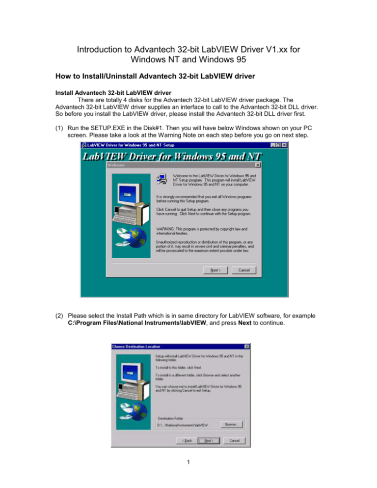
(1) Run the SETUP.EXE in the Disk#1. Then you will have below Windows shown on your PC
screen. Please take a look at the Warning Note on each step before you go on next step.
(2) Please select the Install Path which is in same directory for LabVIEW software, for example
C:\Program Files\National Instruments\labVIEW, and press Next to continue.
1
(3) Before you start to use the Advantech 32-bit LabVIEW driver, please take a look at the
LabVIEW Driver readme file in the Advantech Driver for 95/NT folder.
Uninstall Advantech 32-bit LabVIEW driver
(1) Please enter the Control Panel folder and launch Add/Remove
Programs utility.
(2) Select LabVIEW Driver for Windows 95 and NT item and press Add/Remove… button to
remove the driver form you Windows 95/NT system.
2
How to Find the Advantech’s VIs from LabVIEW Environment
(1) Make sure that the Active Windows is in Diagram mode, Windows Show Diagram (Ctrl +
E)
(2) Eanble the Functions Palette dialog, Windows Show Functions Palette
(3) Click on the Advantech icon, you will find that the Advantech LabVIEW driver is divided by
two main group: Easy I/O VIs and Advanced I/O VIs. For detail usage on the suppoted VIs,
please refer to Advantech LabVIEW Driver User’s Guide.
3
Start from Tutorial Example
Tutorial 1: Get voltage input from PCL-818L
(C:\Program Files\National Instruments\labVIEW\Examples\Examples\Advantech\TUTOR1.VI)
(1) Click on New VI button to create a new LabVIEW program.
(2) Select Front Panel and enable Controls Palette to choose a Waveform Chart indicator in
Graph group, add it to front panel and named it Voltage.
(3) Switch to Block Diagram to verify that a new data terminal was created (named Voltage).
(4) Add a DeviceOpen VI from the Advantech 32-bit LabVIEW driver by clicking on Advantech
VIs. The path to get DeviceOpen VI is Advantech >> Advance >> DeviceManager >>
DeviceOpen.
(5) Move the mouse to the DeviceOpen VI and click on the mouse left button to invoke the
Create Constant function. After creating a constant, a number will appear at the left of
DeviceOpen VI block. Change the value of the constant next to the “DeviceOpen” VI to be 1.
4
(6) Execute the Advantech device installation utility (within Advantech DLL driver) from the
Windows environment to check with the device number of Advantech DEMO I/O virtual demo
board. For example, the device number of Advantech DEMO I/O in the screen shown below is
001.
(7) Add AIConfig and AIVoltageIn, and then change the mouse cursor for use with the Wiring
pattern (move the cursor into Tools Palette and select the Wiring icon) to establish the
linkage. The path to get AIConfig and AIVoltageIn VI is Advantech >> Advance >>
adSlowAI >> AIConfig and AIVoltageIn. The Help window shows input and output
parameters of each selected VI. (The way to display the Help window is to click on the Help
menu selection and select the “Show Help” option)
(8) Add DeviceClose VI, and then establish the linkage.. The path to get DeviceClose” VI is
Advantech >> Advance >> DeviceManager >> DeviceClose.
5
(9) For the AIConfig VI, Channel and Gain are necessary input values. In order to provide
Channel and Gain values for the AIConfig VI, you can add two controls items in Front Panel
and pass their values to the AIConfig VI in Block Diagram.
(10)Create the linkage to show the AI signal to Waveform Chart.
(11)The basic steps to get AIVoltageIn data are now complete. You can switch to the window to
the Front Panel window and click the Run button to execute AIVoltageIn VI.
(12)If your waveform chart does not show the whole graph, you can change the scale of the Yaxis. To change the Y axis scale on the waveform chart, move the cursor to the graphic
origin, click the left mouse button, and type in the desired value.
(13)You can also add a “While Loop” to enhance your program. First, move mouse to Functions
Palette and select the Structures group and the While Loop VI. Add the While Loop VI to
the Block Diagram and enlarge it to include the AIVoltageIn VI and the Voltage data terminal.
(14)Add a Stop button to control the execution of the While Loop. Enable the Front Panel and
move the mouse to Controls Palette. Select the Boolean and Rectangular Stop Button to
add a STOP button to the Front Panel.
6
(15)Switch to Block Diagram. A TF VI should be showing on the Diagram. Move the TF VI into the
While Loop VI and add a NOT VI from Functions Palette. Move NOT VI to the location
between TF VI and COND VI. Wire the output of the TF VI to the input of the NOT VI and wire
the output of the NOT VI to the input of the COND VI. After wiring, switch to Front Panel and
press the RUN button to execute.
(16)If you want to get voltage data from a given device, just change the constant number of the
DeviceOpen VI to be the device number of the device of interest. For example, the device
number of the PCL-812PG in this tutorial is 0.
7
VIs Mapping to API Functions of Advantech 32-bit DLL driver
The Advanced I/O VIs are actually composed of intermediate VIs, which are in turn composed of
advanced VIs.
Advanced I/O VIs
Group
DeviceManager
adSlowAI
adSlowAO
adDIO
adCountTimer
VIs
-
Mapping 32-bit DLL API
DeviceGetNumOfList
DeviceGetList
DeviceGetSubList
BoardName
DeviceOpen
DeviceClose
DeviceGetFeatures
GetErrorMessage
AllocDMABuf
FreeDMABuf
AllocINTBuf
FreeINTBuf
EnableEvent
CheckEvent
AIConfig
AIGetConfig
MAIConfig
TCMuxRead
AIVoltageIn
AIBinaryIn
AIScale
AIVoltageInExp
MAIVolatgeIn
MAIBinaryIn
MAIVoltageInExp
AOConfig
AOVoltageOut
AOScale
AOBinaryOut
DIOSetPortMode
DIOGetConfig
DIOGetCurrentDOBit
DIOGetCurrentDOByte
DIOWriteBit
DIOReadBit
DIOWritePortByte
DIOReadPortByte
WritePortByte
ReadPortByte
WritePortWord
ReadPortWord
outp
outpw
inp
inpw
CounterEventStart
CounterEventRead
CounterFregStart
CounterFregRead
QCounterStart
8
-
DeviceOpen
DeviceClose
DeviceGetFeatures
-
AllocDMABuf
FreeDMABuf
-
EnableEvent
CheckEvent
AIConfig
AIGetConfig
MAIConfig
TCMuxRead
AIVoltageIn
AIBinaryIn
AIScale
AIVoltageInExp
MAIVolatgeIn
MAIBinaryIn
MAIVoltageInExp
AOConfig
AOVoltageOut
AOScale
AOBinaryOut
DIOSetPortMode
DIOGetConfig
DIOGetCurrentDOBit
DIOGetCurrentDOByte
DIOWriteBit
DIOReadBit
DIOWritePortByte
DIOReadPortByte
WritePortByte
ReadPortByte
WritePortWord
ReadPortWord
-
CounterEventStart
CounterEventRead
CounterFregStart
CounterFregRead
QCounterStart
adAlarm
FastAI
FastAO
WatchDog
COM Port
-
QCounterRead
CounterPulseStart
CounterReset
QCounterConfigSys
QCounterConfig
AlarmConfig
AlarmEnable
AlarmCheck
AlarmReset
FAIINTStart
FAIINTScanStart
FAIDMAStart
FAIDMAScanStart
FAIDualDMAStart
FAIDualDMAScanStart
FAITransfer
FAICheck
ClearOverrun
FAIStop
FAOINTStart
FAODMAStart
FAOScale
FAOLoad
FAOCheck
FAOStop
FAIWatchdogCfg
FAIINTWatchdogStart
FAIDMAWatchdogStart
FAIWatchdogCheck
COMOpen
COMClose
COMGetConfig
COMSetConfig
COMRead
COMWrite
COMWrite232
COMWrite485
COMEscape
COMWrite85
9
-
QCounterRead
CounterPulseStart
CounterReset
QCounterConfigSys
QCounterConfig
AlarmConfig
AlarmEnable
AlarmCheck
AlarmReset
FAIINTStart
FAIINTScanStart
FAIDMAStart
FAIDMAScanStart
FAIDualDMAStart
FAIDualDMAScanStart
FAITransfer
FAICheck
-
FAIStop
FAOINTStart
FAODMAStart
FAOScale
FAOLoad
FAOCheck
FAOStop
-
FAIINTWatchdogStart
FAIDMAWatchdogStart
FAIWatchdogCheck
COMOpen
COMClose
COMGetConfig
COMSetConfig
COMRead
COMWrite
COMWrite232
COMWrite485
COMEscape
COMWrite85
Max Speed for Advantech 32-bit LabVIEW driver
Functions
INT/AI
DMA/AI
INT with
INT/AO
DMA/AO
INT/DI
Product
FIFO/AI
Name
MIC-2718
PCL-711
PCL-812PG
PCL-718/818
PCL-816
PCL-818H
PCL-818HD
PCL-818HG
PCL-818L
PCL-1800
PCL-722
PCL-724
PCL-731
PCL-733
PCL-833
PCL-836
PCM-3718
PCM-3724
PCM-3730
Unlisted
Board
The hardware for above test
CPU
Pentium MMX 200
RAM
64 Mbytes
Mother Board
Advantech MIC-2350 (A) / ASUS TX-97 (B)
Test Utility
(1) INT/AI, DMA/AI and INT with FIFO/AI functions are tested by Adint.Vi and Addma.Vi.
(2) INT/AO and DMA/AO functions are tested by Daint.Vi and Dadma.Vi. This test should
apply an Oscilloscope to check the Analog output.
(3) INT/DI function is tested by Fdigin.Vi.
10
How to create a new CIN block to call to Advantech 32-bit DLL Driver
CIN Overview:
The LabVIEW Code Interface Node (CIN) supplies a way for user to link external code
written in a conventional programming language to LabVIEW.
A CIN is a block diagram node associated with a section of source code written in a
conventional programming language. You may compile the source code first and link it to form
executable code. LabVIEW calls the executable code when the node executes, passing input data
from the block diagram to the executable code, and returning data from the executable code to
the block diagram.
Steps for Creating a CIN code under Windows 95
1) Place the CIN block on a Block Diagram
2) Add Input and Output Terminals to the CIN. Press right mouse key and select “Add
Parameter” for each raw (Left is the Input or Initial value, left is the Output)
3) Presses right mouse key and select Create .c File item and modify the code inside.
Please take care of those codes,
/*
* CIN source file
*/
/* Source CIN of adManager.llb\DeviceOpen.vi */
#include <extcode.h>
#include <hosttype.h>
#include <windows.h>
#include "driver.h"
/* stubs for advanced CIN functions */
UseDefaultCINInit
UseDefaultCINDispose
UseDefaultCINAbort
11
UseDefaultCINLoad
UseDefaultCINUnload
UseDefaultCINSave
typedef struct {
LVBoolean Status;
int32 Code;
LStrHandle Source;
} TDSTA;
CIN MgErr CINRun(uInt32 *DevNum, uInt32 *DevHandle, TDSTA *ErrInfo);
CIN MgErr CINRun(uInt32 *DevNum, uInt32 *DevHandle, TDSTA *ErrInfo)
{
int len;
char msg[256], buf[100];
MgErr Err;
ErrInfo->Code = DRV_DeviceOpen(*DevNum, DevHandle);
if(ErrInfo->Code) {
ErrInfo->Status = LVTRUE;
/* Get Error Message */
StrCpy(msg, "DeviceOpen.vi : ");
DRV_GetErrorMessage(ErrInfo->Code, buf);
StrCat(msg, buf);
len = StrLen(msg)+1;
if(Err=NumericArrayResize(uB, 1L, (UHandle *)&(ErrInfo->Source), len)) return Err;
LStrLen(*(ErrInfo->Source)) = len;
StrCpy(LStrBuf(*(ErrInfo->Source)), msg);
}
else {
ErrInfo->Status = LVFALSE;
}
return noErr;
}
4) Set up the compiler environment (under DOS Prompt Windows). Please run below line
to set up the compiler environment. Here C:\VC5.0\DEVSTUDIO\VC\BIN\ is the
directory of VC compiler.
@echo off
�C:\vc5.0\devstudio\vc\BIN\VCVARS32�
�x86
CALL�
5) Compiler the source codes. Create a .LSB file, Devopen.LSB, to be linked to a CIN
block in Labview environment latter.
�/f�
�Devopen.lvm > c.err
Nmake�
Below is the content of Devopen.lvm. Here the filename, Devopen.lvm, could be a
user defined filename. If you want to use standard C or Windows 95 or Windows NT
libraries, define the symbol cinLibraries in a .LVM. The file, ADSAPI32.LIB, is the
header library of C:\WINDOWS\ADSAPI32.DLL.
IDE=VC
12
name=Devopen
type=CIN
cinLibraries=adsapi32.lib
!include $(CINTOOLSDIR)\NTLVSB.MAK
6) Reload Code Resource From …. Press right mouse key to show the POP-UP dialog
box and select Reload Code Resource From ... item.
Please select a proper .LSB file from below dialog box.
13
Trouble Shooting
Q: Why cannot I use QConter feature on the PCL-836 card?
A: Sorry, there is no 3-axis Quadrature Encoder feature on PCL-836, only PCL-833 card
supports those features. Please also refer to the Table 4-1. DLL Functions on Advantech
LabVIEW Driver User’s Guide. For those supported functions, Table 4-1. DLL Functions
shows detail information on it. Because the Advantech 32-bit DLL driver supply an interface to
call to the Advantech 32-bit DLL driver, for more information about how to setup each
parameter, you can also refer to the Advantech 32-bit DLL driver for Windows NT/95 Ver.
1.00 for relative information.
Q: Why cannot I setup the pulse width of output pluse on the PCL-818 serial cards?
A: Sorry, only PCL-836 card supports this function.
Q: Although I have enabled the Alarm function through ADAM utility, I cannot use the Alarm
function when I try on the Alarm.VI.
A: To use the Alarm function, you should enable the Alarm function from the setup in Device
Installation utility.
Q: I cannot use the LabVIEW driver after I install the Advantech LabVIEW driver into my
system.
A: Please make sure that you have installed the Advantech LabVIEW driver into the same
directory where you install the LabVIEW software, \Program Files\National
Instruments\LabVIEW\.
Q: I cannot use the Analog Output with DMA on PCL-1800 and PCL-816.
A: Please check with the Hardware User’s Manual on these two cards, the Analog Output
channel with DMA transfer is Channel 1 for PCL-1800, and Channel 0 for PCL-816.
Q: Could you please inform us detail information on the Watchdog feature of PCL-1800 card.
A: ???
Q: How can I perform Direct I/O function and receive Interrupt Event through LabVIEW
driver.
A: Please refer to the example, PORTIO.VI and FDIGIT.VI.
Q: How can I use the Advantech LabVIEW driver to communicate with PLC device through
COM port.
A: Please refer to the example, COMMPORT.VI, which can send up to 256 characters on
each time you send command string to COM port.
Q: How can I implement my own CIN block to call to Advantech 32-bit DLL driver.
A: Please refer to the following topic in this document,
How to create a new CIN block to call to Advantech 32-bit DLL Driver
14
If this document cannot fit your requirement, please refer to below two manaul. Because
Advantech Co. is a company of LabVIEW driver vender, for detail technology consultation,
please contact you LabVIEW software provider.
Advantech 32-bit DLL driver for Windows NT/95 Ver. 1.00
LabVIEW Code Interface Reference Manual
15
Reference Books
Advantech 32-bit DLL driver for Windows NT/95 Ver. 1.00, MANUAL.DOC 1
Advantech LabVIEW Driver User’s Guide (Windows 95/NT), LVMANUAL.DOC2
LabVIEW User’s Manual
LabVIEW Code Interface Reference Manual
1
You can find this file in \Program Files\Advantech\Adsapi\ directory.
2
You can find this file in \Program Files\National Instruments \LabVIEW\ directory.
16
