Engineering Bulletin
PUROLITE® C100
Sodium Cycle Operation
Purolite C100 is a premium industrial grade, gel polystyrenic strong acid cation exchange
resin, supplied in the sodium form. Its principal application in the sodium form is in industrial
water softening. Due to its robust nature Purolite C100 is also used as a cation exchanger in
demineralization plants, where it is operated in the hydrogen form following full acid
regeneration.
This document refers specifically to the resin use in water softening, for the removal of total
hardness, with sodium chloride (salt) regeneration. For its use as cation exchange resin in
demineralization processes, please refer to the Purolite C100 Hydrogen Cycle Engineering
Bulletins.
Purolite C100 has a standard particle size distribution and it is primarily used in co-flow and
traditional counter-flow regenerated softening units. It operates successfully over a wide range
of operating conditions and it offers a higher resistance to the attack by oxidizing agents, such
as chlorine, compared to some other less robust softening resins, resulting in a longer resin life.
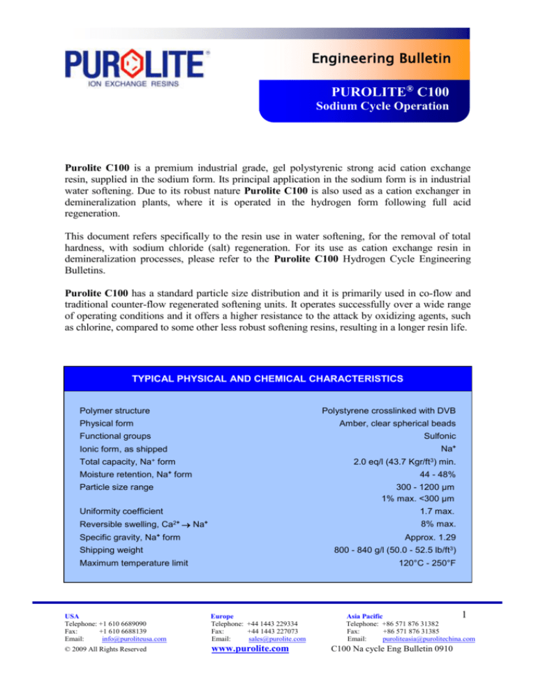
TYPICAL PHYSICAL AND CHEMICAL CHARACTERISTICS
Polymer structure
Polystyrene crosslinked with DVB
Physical form
Amber, clear spherical beads
Functional groups
Sulfonic
Na+
Ionic form, as shipped
Total capacity, Na+ form
2.0 eq/l (43.7 Kgr/ft3) min.
+
Moisture retention, Na form
44 - 48%
Particle size range
300 - 1200 µm
1% max. <300 µm
Uniformity coefficient
1.7 max.
Reversible swelling, Ca2+ Na+
8% max.
+
Specific gravity, Na form
Approx. 1.29
800 - 840 g/l (50.0 - 52.5 lb/ft3)
Shipping weight
Maximum temperature limit
120°C - 250°F
USA
Telephone: +1 610 6689090
Fax:
+1 610 6688139
Email:
info@puroliteusa.com
Europe
Telephone: +44 1443 229334
Fax:
+44 1443 227073
Email:
sales@purolite.com
© 2009 All Rights Reserved
www.purolite.com
1
Asia Pacific
Telephone: +86 571 876 31382
Fax:
+86 571 876 31385
Email:
puroliteasia@purolitechina.com
C100 Na cycle Eng Bulletin 0910
Available Grades
Purolite C100 is available in different grades, all supplied in the Na+ form.
-
-
-
-
Purolite C100 is a standard grade resin with a Gaussian particle size distribution in the
range 300-1200 μm. Its principal application is in co-flow and traditional counter-flow
regenerated softening and demineralization plants, where classification of the bed inside the
operating vessel is possible.
Purolite C100C is a modified grade with a particle size in the range 400-1200 μm, for use
in high flow rate applications where the standard grade resin would present an unacceptably
high pressure drop across the bed.
Purofine® PFC100 is a Uniform Particle Size product with a mean particle size of 570 µm
and a UC of 1.1-1.2, offering improved performance in softening and demineralisation
systems, with regard to capacity, leakage, pressure drop and rinse water requirements.
Puropack PPC100 is another Uniform Particle Size product, offering similar advantages,
but with a mean particle size of 650 µm. This product has been specifically developed for
the PUROPACK® system and other packed bed counter-flow designs employing either upflow or down-flow service operation. Both Purofine® PFC100 and Puropack® PPC100
have also seen successful operation in short cycle plants.
Purolite C100DL is a specially designed, coarse grade resin, with a particle size range of
630-1200 μm. Its principal application is in layered bed cation exchange units in
conjunction with a DL grade Purolite weak acid cation resin such as Purolite
C104DLPlus.
Purolite C100S is a specially cleaned and trimmed food grade resin with a particle size in
the range 400-1200 μm, for use in food processing, such as in the sugar industry.
Typical Operating Data (Guide to Service Operation and Regeneration)
Service Operation
In service operation hard water is normally pumped through the resin bed, which is retained
within a pressure vessel. The vessel has top and bottom distribution / collection systems. These
systems are designed to ensure the raw water passes evenly through the ion exchange bed in
service operation. As the water passes through the resin, the hardness (principally calcium and
magnesium) is exchanged with sodium ions. Hence the treated softened water has a higher
sodium content and a somewhat higher conductivity. When the resin is exhausted it is then
regenerated with a NaCl solution to put the resin back into the sodium form, ready for the next
service operation. Therefore the internal systems also have to efficiently distribute and collect
the regenerant brine solution, rinses, etc.
USA
Telephone: +1 610 6689090
Fax:
+1 610 6688139
Email:
info@puroliteusa.com
Europe
Telephone: +44 1443 229334
Fax:
+44 1443 227073
Email:
sales@purolite.com
© 2009 All Rights Reserved
www.purolite.com
2
Asia Pacific
Telephone: +86 571 876 31382
Fax:
+86 571 876 31385
Email:
puroliteasia@purolitechina.com
C100 Na cycle Eng Bulletin 0910
In service operation optimum performance is achieved at service flow rates between 8 and 40
BV/h (Bed Volumes per hour) or 1 to 5 gpm/ft3 (US gallons per minute per cubic foot of resin)
within linear flow rates (velocities) of 10 to 50 m3/m2/h (m/h) or 4 to 20 gpm/ft2 (US gallons
per minute per square foot of vessel cross section), whereas brine regeneration is carried out at
flow rates of 2 to 4 BV/h or 0.25 to 0.5 gpm/ft3. Within these limits internal distribution /
collection systems can operate efficiently both at the higher service and lower regenerant flow
rates. At very low service flow rates channelling can occur within the resin bed resulting in
poor plant performance and short capacity between regenerations. This is particularly likely
when long service cycles are also employed at these low flow rates.
While some small industrial and domestic softeners operate with very shallow bed depths, bed
depths below 610 mm (2 ft) should be avoided and preferably bed depths greater than 1000 mm
(3 ft 3 in) employed. Vessel height and pressure drop are normally the controlling factor on the
maximum height of the bed. For Purolite C100 we recommend that pressure drop across the
bed should be maintained at less than 150 kPa (22 psi), having made allowance for bed
compaction and any solids loading across a classified bed. Bed depths greater than 2000 mm
(6 ft 6 in) are rarely encountered. The ratio of height to diameter is important in any ion
exchange unit design.
Although smaller freeboards are sometimes encountered, we recommend a minimum 75%
freeboard (space) above the resin bed to allow at least 50% bed expansion during backwash.
This is normally adequate for a co-flow regenerated vessel, and assures a good hydraulic
classification of the resin bed.
Service operation is usually terminated by detection of hardness leakage, or volumetric
throughput (water meter control), or on a time basis (time clock control). Regeneration can be
manually or automatically initiated via the control system.
While co-flow regenerated resin beds with backwashing will tolerate a low level of suspended
solids present in the incoming water supply, the resin bed should not be expected to work as a
mechanical filter. Adequate pre-treatment should always be included if optimum resin
performance is required.
Regeneration
The resin regeneration can be performed either co-flow or counter-flow. The regeneration is
termed co-flow when the regenerant flows through the resin bed in the same direction,
normally downwards or “top to bottom”, in which the water flows during the service operation.
When the regenerant flow is in the opposite direction to service flow, then the term used is
counter-flow regeneration. Other terms such as co-current and counter-current are also used to
describe these two principal regeneration techniques.
USA
Telephone: +1 610 6689090
Fax:
+1 610 6688139
Email:
info@puroliteusa.com
Europe
Telephone: +44 1443 229334
Fax:
+44 1443 227073
Email:
sales@purolite.com
© 2009 All Rights Reserved
www.purolite.com
3
Asia Pacific
Telephone: +86 571 876 31382
Fax:
+86 571 876 31385
Email:
puroliteasia@purolitechina.com
C100 Na cycle Eng Bulletin 0910
It should be remembered when counter-flow regeneration is employed, it is important that in
the up flow stage(s) the bed must remain static and hence packed beds, air hold down, split
flow and water hold down are just some of the systems employed to achieve this requirement.
Co-flow regeneration
The co-flow regeneration technique is normally made up of 5 steps and typically takes between
1 and 2 hours depending on the detailed design. For this type of regeneration, the influent water
is usually of adequate quality for all steps, including regenerant dilution.
The first step of co-flow regeneration is backwash. The backwash water enters the unit through
the bottom collection / distribution system, loosening the bed and causing the bed to expand as
the water passes up through it. The flow rate should be set for the freeboard available in the unit
at the minimum water temperature. The backwash is designed to both decompact the resin, for
better regenerant contact, as well as for removing any suspended solids that have been filtered
out of the incoming supply and accumulated within the bed. The backwash water volume
required will depend on the extent of solids loading. Where the bed only requires loosening for
better regenerant contact then 1 FBV (free board volume) is normally sufficient. However,
when filtered solids are present the volume required can be considerably greater. After the
backwash a “bed settle” step is required.
The bed settle allows the resin to settle back and reform the static bed prior to regenerant
injection. Depending on the size of the bed, free board, and backwash rate used, this step can
take between 3 and 8 minutes.
Regenerant injection at the correct flow rate and brine concentration are critical. Good contact
between the NaCl solution (brine) and the resin is essential for optimum performance. Purolite
recommend the brine is introduced at 10% concentration. Experience shows that at
concentrations above and below this strength a small loss in performance can be expected. The
brine should be introduced at 2 to 4 BV/h (0.25 to 0.5 gpm/ft3) and the regeneration level
(amount of NaCl per litre of resin) employed will typically be between 80 and 160 g/l (5 – 10
lb/ft3), though regeneration levels as low as 50 g/l (3 lb/ft3) and as high as 250 g/l (16 lb/ft3)
have been employed.
The slow (regenerant displacement) rinse is always carried out at flow rates similar to the brine
injection step. This is to ensure, first, a uniform contact time between the resin and the
regenerant solution and, second, that the rinse water follows the same route of the regenerant
through the resin bed. As slow rinses are usually more efficient in removing the spent
regenerant from the resin, the more slow rinsing employed can be beneficial in reducing the
amount of final rinse required at the end of the regeneration. Normally 1 to 3 BV (7.5 to 22.5
gal/ft3) of slow rinse are applied.
The final rinse is often carried out at the service flow rate and this also acts as a proving
condition prior to returning to service after regeneration. On some occasions, where flow
USA
Telephone: +1 610 6689090
Fax:
+1 610 6688139
Email:
info@puroliteusa.com
Europe
Telephone: +44 1443 229334
Fax:
+44 1443 227073
Email:
sales@purolite.com
© 2009 All Rights Reserved
www.purolite.com
4
Asia Pacific
Telephone: +86 571 876 31382
Fax:
+86 571 876 31385
Email:
puroliteasia@purolitechina.com
C100 Na cycle Eng Bulletin 0910
restrictions occur, the plant final rinse is carried out at a lower than the service flow rate.
Normally 3 to 6 BV (22.5 to 45 gal/ft3) are required depending on the design of the distribution
/ collection system and the amount of slow rinsing previously performed.
Typical Operating Conditions for Co-flow Regeneration
Step
Design Basis
Duration
Backwash
Set for minimum water temperature to
give 50% bed expansion
1 FBV on clean water supplies and
2-3 FBV where solids are present
Bed settle
To allow the bed to reform fully
classified
3 to 8 minutes
NaCl injection
50-250 g/l (3-15 lb/ft3) applied as a
10% brine solution at 2-4 BV/h (0.25 to
0.5 gpm/ft3)
Typically 20-45 minutes depending
on regeneration level and flow rate
Slow rinse
1-3 BV (7.5 to 22.5 gal/ft3) at approx.
regenerant flow rate
Typically 20-45 minutes depending
on volume of water applied and
flow rate
Final rinse
3-6 BV (22.5 to 45 gal/ft3) preferably
at service flow rate or alternatively >
15 BV/h (2 gpm/ft3)
Typically 10-20 minutes
(Key: BV = Bed Volume, BV/h = Bed Volume per hour, FBV = Free board volume above resin bed)
Counter-flow regeneration
While counter-flow regeneration can also be applied to Purolite C100, this technique is often
used with other more specialised grades of Purolite cation resin to enhance the performance
further. Consult your local Purolite sales office for guidance.
In counter-flow regeneration bed depths below 1000 mm (3 ft 3 in) should be avoided and
preferably beds in excess of 1200 mm (4 ft) employed.
The traditional counter-flow regeneration technique is normally made up of 3 steps, as opposed
to the 5 steps described earlier for co-flow regeneration, and typically takes between 1 and 2
hours depending on the detailed design. This type of regeneration requires the use of a water
free from hardness for the brine make up, injection and the slow rinse steps if the published
leakage is to be obtained. The softened water produced by the same plant is usually adequate,
USA
Telephone: +1 610 6689090
Fax:
+1 610 6688139
Email:
info@puroliteusa.com
Europe
Telephone: +44 1443 229334
Fax:
+44 1443 227073
Email:
sales@purolite.com
© 2009 All Rights Reserved
www.purolite.com
5
Asia Pacific
Telephone: +86 571 876 31382
Fax:
+86 571 876 31385
Email:
puroliteasia@purolitechina.com
C100 Na cycle Eng Bulletin 0910
and the required quantity is either set aside during the previous service run or, in case of twoline units, supplied by the other on-line unit.
In a counter-flow regenerated system, the backwash, that always represents the first step of coflow regeneration, is not normally performed each cycle. Some engineering designs allow for
subsurface backwash or periodic full bed backwash, either inside the service unit or in separate
external dedicated towers. In the vast majority of designs backwash is not part of the standard
regeneration, although it should be included in the design of the unit. After a full bed backwash
the resin should be regenerated with double the normal amount of brine to restore full
performance.
The regenerant brine should be introduced at 2 to 4 BV/h (0.25 to 0.5 gpm/ft3) and the
regeneration level (amount of NaCl per litre of resin) employed will typically be lower than for
co-current regenerated units, typically between 50 and 150 g/l (3 – 9 lb/ft3).
The slow (regenerant displacement) rinse is always carried out at flow rates similar to the brine
injection step and in the same direction. This is to ensure, first, a uniform contact time between
the resin and the regenerant solution and, second, that the rinse water follows the same route of
the regenerant through the resin bed. As slow rinses are usually more efficient in removing the
spent regenerant from the resin, the more slow rinsing employed can reduce the amount of final
rinse required. Normally 1 to 2 BV (7.5 to 15 US gal/ft3) of slow rinse are adequate.
The final rinse is often carried out at the service flow rate and this also acts as a proving
condition prior to returning to service after regeneration. Normally 2 to 4 BV (15 to 30 gal/ft3)
are required depending on the design of the distribution / collection system and the amount of
slow rinsing previously performed.
Typical Operating Conditions for Counter-flow Regeneration
Step
Design Basis
Duration
NaCl injection
50-150 g/l (3-10 lb/ft3) applied as a
10% brine solution at 2-4 BV/h (0.25
to 0.5 gpm/ft3)
Typically 20-45 minutes depending
on regeneration level and flow rate
Slow rinse
1-2 BV (7.5 to 15 gal/ft3) at approx.
regenerant flow rate
Typically 20-45 minutes depending
on volume of water applied and flow
rate
Final rinse
2-4 BV (15 to 30 gal/ft3) preferably at
service flow rate or alternatively > 15
BV/h (2 gpm/ft3)
Typically 10-20 minutes
(Key: BV = Bed Volume, BV/h = Bed Volume per hour)
USA
Telephone: +1 610 6689090
Fax:
+1 610 6688139
Email:
info@puroliteusa.com
Europe
Telephone: +44 1443 229334
Fax:
+44 1443 227073
Email:
sales@purolite.com
© 2009 All Rights Reserved
www.purolite.com
6
Asia Pacific
Telephone: +86 571 876 31382
Fax:
+86 571 876 31385
Email:
puroliteasia@purolitechina.com
C100 Na cycle Eng Bulletin 0910
Performance Data
The following data are designed to help the design engineer to estimate the exchange capacity
and hardness leakage achieved with Purolite C100 under different operating conditions. All
the data shown are the result of years of industrial experience and are supplied in total good
faith, but the final performance will equally depend on the detailed design and operation of the
system, the quality of the regenerant chemicals as well as the long term maintenance of the
plant. Some engineers who are using basic, standard plant of simple design may wish to take a
design margin (safety factor) with regard to the published data to allow for less than ideal
operation. Please note the data presented in this section are specific to co-flow regenerated
designs with bed depths over 1000 mm (3 ft 3 in) and counter-flow regenerated designs with
bed depths over 1200 mm (6 ft 6 in). For shallower bed depths there may be a requirement to
down rate the expected performance depending on the quality of the design.
The data supplied are divided in three groups: figures 1 to 9 deal with capacity and leakage for
co-flow regeneration, figures 10 to 18 with capacity and leakage for counter-flow regeneration
and figures 19 to 20 with hydraulic data (backwash expansion and pressure drop). Within each
of the first two groups there is a base capacity and a base leakage curve, both followed by other
curves showing correction factors. To calculate the expected capacity or leakage, multiply the
base capacity or leakage by the relevant correction factors.
For users interested in performing these engineering calculations electronically, Purolite’s
PureDesign™ software is available for download via www.purolite.com at no charge.
The data presented in this bulletin can also be used to estimate the operating performances of
resins such as Purolite C100C, Purolite C100S or Purolite C100DL, while it is
recommended to refer to dedicated engineering bulletins for products like Purofine® PFC100
and Puropack® PPC100.
USA
Telephone: +1 610 6689090
Fax:
+1 610 6688139
Email:
info@puroliteusa.com
Europe
Telephone: +44 1443 229334
Fax:
+44 1443 227073
Email:
sales@purolite.com
© 2009 All Rights Reserved
www.purolite.com
7
Asia Pacific
Telephone: +86 571 876 31382
Fax:
+86 571 876 31385
Email:
puroliteasia@purolitechina.com
C100 Na cycle Eng Bulletin 0910
Co-flow regeneration
Figure 1
Base capacity (co-flow regeneration)
Regeneration level, lb NaCl/ft3
0
2
4
6
8
10
12
14
16
18
1.8
38
1.6
1.4
28
1.2
23
1.0
Base capacity, Kgr/ft3
Base capacity, eq/l
33
18
0.8
0.6
0
50
100
150
200
250
13
300
Regeneration level, g NaCl/l
USA
Telephone: +1 610 6689090
Fax:
+1 610 6688139
Email:
info@puroliteusa.com
Europe
Telephone: +44 1443 229334
Fax:
+44 1443 227073
Email:
sales@purolite.com
© 2009 All Rights Reserved
www.purolite.com
8
Asia Pacific
Telephone: +86 571 876 31382
Fax:
+86 571 876 31385
Email:
puroliteasia@purolitechina.com
C100 Na cycle Eng Bulletin 0910
Co-flow regeneration
Figure 2
C1 - Capacity correction factor for influent TH
Influent TH, gr/gal as CaCO3
0
20
40
60
80
100
120
140
1.00
C1
0.95
0.90
0.85
0
10
20
30
40
50
Influent TH, meq/l
Figure 3
C2 - Capacity correction factor for service flow rate
Service flow rate, gpm/ft3
0
2
4
6
8
10
12
1.1
C2
1.0
0.9
0.8
0.7
0
20
40
60
80
100
Service flow rate, BV/h
USA
Telephone: +1 610 6689090
Fax:
+1 610 6688139
Email:
info@puroliteusa.com
Europe
Telephone: +44 1443 229334
Fax:
+44 1443 227073
Email:
sales@purolite.com
© 2009 All Rights Reserved
www.purolite.com
9
Asia Pacific
Telephone: +86 571 876 31382
Fax:
+86 571 876 31385
Email:
puroliteasia@purolitechina.com
C100 Na cycle Eng Bulletin 0910
Co-flow regeneration
Figure 4
C3 - Capacity correction factor for influent Na
Influent Na, gr/gal as CaCO3
0
20
40
60
80
100
120
140
1.00
C3
0.95
0.90
0.85
0
10
20
30
40
50
Influent Na, meq/l
Figure 5
C4 - Capacity correction factor for brine concentration
1.02
1.00
C4
0.98
0.96
0.94
0.92
0
5
10
15
20
25
Brine concentration, %
USA
Telephone: +1 610 6689090
Fax:
+1 610 6688139
Email:
info@puroliteusa.com
Europe
Telephone: +44 1443 229334
Fax:
+44 1443 227073
Email:
sales@purolite.com
© 2009 All Rights Reserved
www.purolite.com
10
Asia Pacific
Telephone: +86 571 876 31382
Fax:
+86 571 876 31385
Email:
puroliteasia@purolitechina.com
C100 Na cycle Eng Bulletin 0910
Co-flow regeneration
Figure 6
Base hardness leakage
Regeneration level, lb NaCl/ft3
Base leakage, ppm CaCO3
0
2
4
6
8
10
12
14
16
18
4.0
3.0
2.0
1.0
0.0
0
50
100
150
200
250
300
Regeneration level, g NaCl/l
Figure 7
L1 - Leakage correction factor for Na / Total Cations
3.0
2.5
L1
2.0
1.5
1.0
0.5
0.0
0
20
40
60
80
100
Na/TC, %
USA
Telephone: +1 610 6689090
Fax:
+1 610 6688139
Email:
info@puroliteusa.com
Europe
Telephone: +44 1443 229334
Fax:
+44 1443 227073
Email:
sales@purolite.com
© 2009 All Rights Reserved
www.purolite.com
11
Asia Pacific
Telephone: +86 571 876 31382
Fax:
+86 571 876 31385
Email:
puroliteasia@purolitechina.com
C100 Na cycle Eng Bulletin 0910
Co-flow regeneration
Figure 8
L2 - Leakage correction factor for Total Hardness
Influent TH, gr/gal as CaCO3
0
10
20
30
40
50
60
70
2.5
2.0
L2
1.5
1.0
0.5
0.0
0
5
10
15
20
25
Influent TH, meq/l
Figure 9
L3 - Leakage correction factor for
Total Dissolved Solids
TDS, gr/gal as CaCO3
0
20
40
60
80
100
120
140
10
L3
8
6
4
2
0
0
10
20
30
40
50
TDS, meq/l
USA
Telephone: +1 610 6689090
Fax:
+1 610 6688139
Email:
info@puroliteusa.com
Europe
Telephone: +44 1443 229334
Fax:
+44 1443 227073
Email:
sales@purolite.com
© 2009 All Rights Reserved
www.purolite.com
12
Asia Pacific
Telephone: +86 571 876 31382
Fax:
+86 571 876 31385
Email:
puroliteasia@purolitechina.com
C100 Na cycle Eng Bulletin 0910
Counter-flow regeneration
Figure 10
Base capacity (counter-flow regeneration)
Regeneration level, lb NaCl/ft3
2.5
3.5
4.5
5.5
6.5
7.5
8.5
9.5
1.8
38
1.6
1.4
28
1.2
23
1.0
Base capacity, Kgr/ft
Base capacity, eq/l
3
33
18
0.8
0.6
40
60
80
100
120
140
13
160
Regeneration level, g NaCl/l
USA
Telephone: +1 610 6689090
Fax:
+1 610 6688139
Email:
info@puroliteusa.com
Europe
Telephone: +44 1443 229334
Fax:
+44 1443 227073
Email:
sales@purolite.com
© 2009 All Rights Reserved
www.purolite.com
13
Asia Pacific
Telephone: +86 571 876 31382
Fax:
+86 571 876 31385
Email:
puroliteasia@purolitechina.com
C100 Na cycle Eng Bulletin 0910
Counter-flow regeneration
Figure 11
C1 - Capacity correction factor for Total Hardness
Influent TH, gr/gal as CaCO3
0
20
40
60
80
100
120
140
1.00
C1
0.96
0.92
0.88
0.84
0
10
20
30
40
50
Influent TH, meq/l
Figure 12
C2 - Capacity correction factor for service flow rate
Service flow rate, gpm/ft3
0
1
2
3
4
5
6
7
8
1.05
C2
1.00
0.95
0.90
0
10
20
30
40
50
60
70
Service flow rate, BV/h
USA
Telephone: +1 610 6689090
Fax:
+1 610 6688139
Email:
info@puroliteusa.com
Europe
Telephone: +44 1443 229334
Fax:
+44 1443 227073
Email:
sales@purolite.com
© 2009 All Rights Reserved
www.purolite.com
14
Asia Pacific
Telephone: +86 571 876 31382
Fax:
+86 571 876 31385
Email:
puroliteasia@purolitechina.com
C100 Na cycle Eng Bulletin 0910
Counter-flow regeneration
Figure 13
C3 - Capacity correction factor for resin bed depth
Bed depth, in
20
40
60
80
100
120
0.5
1.0
1.5
2.0
2.5
3.0
1.20
C3
1.10
1.00
0.90
0.80
Bed depth, m
Figure 14
C4 - Capacity correction factor for brine concentration
1.02
1.00
C4
0.98
0.96
0.94
0.92
0
5
10
15
20
25
Brine concentration, %
USA
Telephone: +1 610 6689090
Fax:
+1 610 6688139
Email:
info@puroliteusa.com
Europe
Telephone: +44 1443 229334
Fax:
+44 1443 227073
Email:
sales@purolite.com
© 2009 All Rights Reserved
www.purolite.com
15
Asia Pacific
Telephone: +86 571 876 31382
Fax:
+86 571 876 31385
Email:
puroliteasia@purolitechina.com
C100 Na cycle Eng Bulletin 0910
Counter-flow regeneration
Figure 15
Base hardness leakage
Regeneration level, lb NaCl/ft3
Base leakage, ppm CaCO3
2.5
3.5
4.5
5.5
6.5
7.5
8.5
9.5
0.8
0.6
0.4
0.2
0
40
60
80
100
120
140
160
Regeneration level, g NaCl/l
Figure 16
L1 - Leakage correction factor for Na / Total Cations
3.0
2.5
L1
2.0
1.5
1.0
0.5
0.0
0
20
40
60
80
100
Na / TC, %
USA
Telephone: +1 610 6689090
Fax:
+1 610 6688139
Email:
info@puroliteusa.com
Europe
Telephone: +44 1443 229334
Fax:
+44 1443 227073
Email:
sales@purolite.com
© 2009 All Rights Reserved
www.purolite.com
16
Asia Pacific
Telephone: +86 571 876 31382
Fax:
+86 571 876 31385
Email:
puroliteasia@purolitechina.com
C100 Na cycle Eng Bulletin 0910
Counter-flow regeneration
Figure 17
L2 - Leakage correction factor for Total Hardness
Influent TH, gr/gal as CaCO3
0
10
20
30
40
50
60
70
1.2
L2
0.8
0.4
0.0
0
5
10
15
20
25
Influent TH, meq/l
Figure 18
L3 - Leakage correction factor for
Total Dissolved Solids
TDS, gr/gal as CaCO3
0
20
40
60
80
100
120
140
10
L3
8
6
4
2
0
0
10
20
30
40
50
TDS, meq/l
USA
Telephone: +1 610 6689090
Fax:
+1 610 6688139
Email:
info@puroliteusa.com
Europe
Telephone: +44 1443 229334
Fax:
+44 1443 227073
Email:
sales@purolite.com
© 2009 All Rights Reserved
www.purolite.com
17
Asia Pacific
Telephone: +86 571 876 31382
Fax:
+86 571 876 31385
Email:
puroliteasia@purolitechina.com
C100 Na cycle Eng Bulletin 0910
Hydraulic characteristics
Figure 19
Backwash expansion
Linear flow rate, gpm/ft2
0
2
4
6
8
10
12
14
Bed expansion, %
120
100
80
60
5°C / 41°F
10°C / 50°F
20°C / 68°F
30°C / 86°F
40
20
0
0
5
10
15
20
25
30
35
Linear flow rate, m/h
Figure 20
Pressure drop
Linear flow rate, gpm/ft2
0
5
10
15
20
4.0
10°C / 50°F
20°C / 68°F
30°C / 86°F
40°C / 104°F
80
60
3.0
2.0
40
20
1.0
0
0.0
0
10
20
30
40
50
Pressure drop, psi/ft
Pressure drop, kPa/m
100
60
Linear flow rate, m/h
USA
Telephone: +1 610 6689090
Fax:
+1 610 6688139
Email:
info@puroliteusa.com
Europe
Telephone: +44 1443 229334
Fax:
+44 1443 227073
Email:
sales@purolite.com
© 2009 All Rights Reserved
www.purolite.com
18
Asia Pacific
Telephone: +86 571 876 31382
Fax:
+86 571 876 31385
Email:
puroliteasia@purolitechina.com
C100 Na cycle Eng Bulletin 0910
Additional information & application notes
Safety: Strong oxidants, such as nitric acid, may cause violent reactions with ion exchange resins under certain
conditions. Use of strong oxidants must be done under the care and supervision of persons knowledgeable in
handling these types of materials.
MSDS/SDS: Material Safety Data Sheets/Safety Data Sheets are available on Purolite’s website,
www.purolite.com. MSDS sheets should be consulted for additional information on product safety, handling and
disposal.
Storage and Transportation: Information on the proper storage and transportation can be found on Purolite’s
website, www.purolite.com.
Notice: The information contained in this document, including application, technical specifications and operation
utilizing Purolite products is provided in good faith and without warranty. Use of our products is out of our
control. It is important that you test our products for suitability in your application and environment. Testing
should include health, safety and material handling as well as application. Unless otherwise agreed, all products
are sold according to our General Terms and Conditions of sale. It is expressly understood that you undertake all
responsibility and liability for use of the product. No license is implied or in fact granted under the claims of any
patent. No other warranty of any kind, express or implied, whether of fitness or merchantability is made as to the
material sold or any instructions or technical advice provided, unless separately agreed in writing.
USA
Telephone: +1 610 6689090
Fax:
+1 610 6688139
Email:
info@puroliteusa.com
Europe
Telephone: +44 1443 229334
Fax:
+44 1443 227073
Email:
sales@purolite.com
© 2009 All Rights Reserved
www.purolite.com
19
Asia Pacific
Telephone: +86 571 876 31382
Fax:
+86 571 876 31385
Email:
puroliteasia@purolitechina.com
C100 Na cycle Eng Bulletin 0910
USA
Telephone: +1 610 6689090
Fax:
+1 610 6688139
Email:
info@puroliteusa.com
Europe
Telephone: +44 1443 229334
Fax:
+44 1443 227073
Email:
sales@purolite.com
© 2009 All Rights Reserved
www.purolite.com
20
Asia Pacific
Telephone: +86 571 876 31382
Fax:
+86 571 876 31385
Email:
puroliteasia@purolitechina.com
C100 Na cycle Eng Bulletin 0910


