NSYV 200, 250, 300 Specs
advertisement
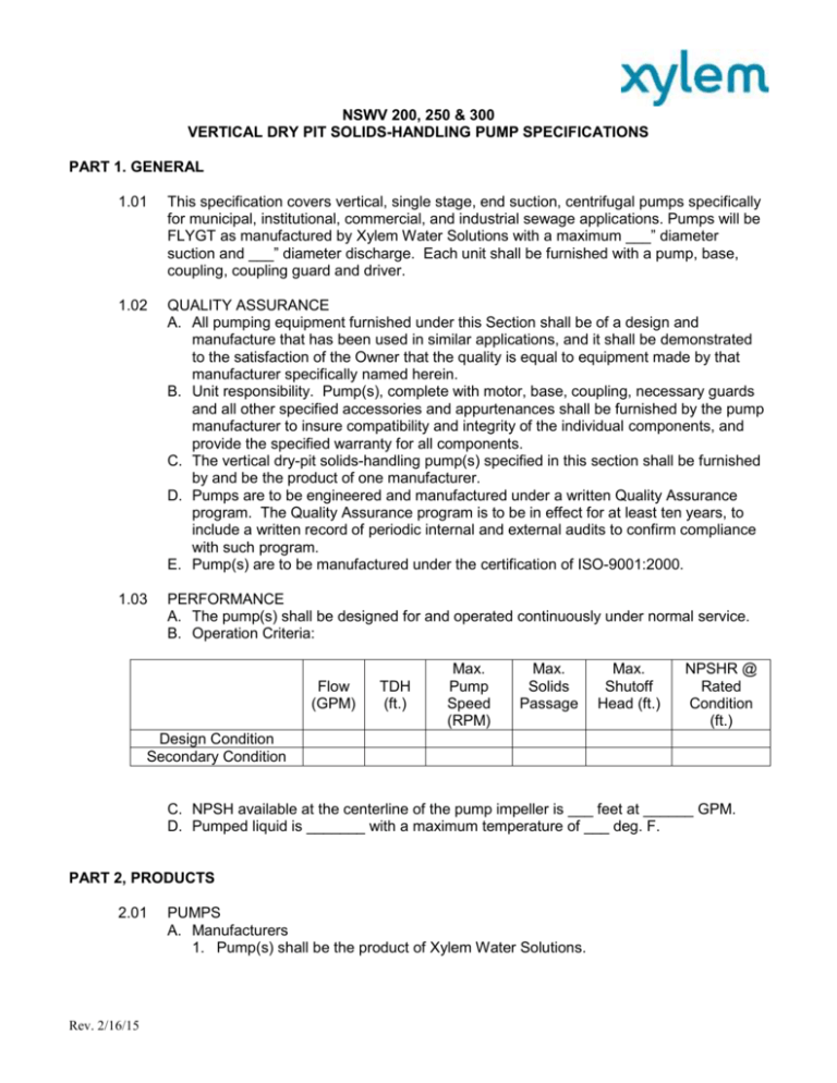
NSWV 200, 250 & 300 VERTICAL DRY PIT SOLIDS-HANDLING PUMP SPECIFICATIONS PART 1. GENERAL 1.01 This specification covers vertical, single stage, end suction, centrifugal pumps specifically for municipal, institutional, commercial, and industrial sewage applications. Pumps will be FLYGT as manufactured by Xylem Water Solutions with a maximum ___” diameter suction and ___” diameter discharge. Each unit shall be furnished with a pump, base, coupling, coupling guard and driver. 1.02 QUALITY ASSURANCE A. All pumping equipment furnished under this Section shall be of a design and manufacture that has been used in similar applications, and it shall be demonstrated to the satisfaction of the Owner that the quality is equal to equipment made by that manufacturer specifically named herein. B. Unit responsibility. Pump(s), complete with motor, base, coupling, necessary guards and all other specified accessories and appurtenances shall be furnished by the pump manufacturer to insure compatibility and integrity of the individual components, and provide the specified warranty for all components. C. The vertical dry-pit solids-handling pump(s) specified in this section shall be furnished by and be the product of one manufacturer. D. Pumps are to be engineered and manufactured under a written Quality Assurance program. The Quality Assurance program is to be in effect for at least ten years, to include a written record of periodic internal and external audits to confirm compliance with such program. E. Pump(s) are to be manufactured under the certification of ISO-9001:2000. 1.03 PERFORMANCE A. The pump(s) shall be designed for and operated continuously under normal service. B. Operation Criteria: Flow (GPM) TDH (ft.) Max. Pump Speed (RPM) Max. Solids Passage Max. Shutoff Head (ft.) NPSHR @ Rated Condition (ft.) Design Condition Secondary Condition C. NPSH available at the centerline of the pump impeller is ___ feet at ______ GPM. D. Pumped liquid is _______ with a maximum temperature of ___ deg. F. PART 2, PRODUCTS 2.01 Rev. 2/16/15 PUMPS A. Manufacturers 1. Pump(s) shall be the product of Xylem Water Solutions. 2. Manufacturer shall have installations of like or similar application with a minimum of 40 years service for this pump size. B. Design 1. Rotation a. The pump will be (clockwise)(counterclockwise) rotation when looking at the pump from the drive end. 2. Impeller a. The impeller shall be single-suction enclosed type with two vanes, made of close grained 2-3% Ni Cast Iron. Impeller be specifically designed with smooth water passages to prevent clogging by stringy or fibrous materials, and shall be capable of passing solids having a maximum sphere size of ____ inches. b. The impeller shall be dynamically balanced, taper bored and keyed to the shaft by a 18-8 stainless steel nut locked in place. It shall be readily removed without the use of special tools. 3. Casing a. The casing shall be close-grained cast iron conforming to ASTM A48 Class 30 of sufficient strength, weight and metal thickness to insure long life, accurate alignment, and reliable operation. The volute shall have smooth fluid passages large enough at all points to pass any size solid which can pass through the impeller and provide smooth unobstructed flow. b. The casing shall be flanged tangential discharge and capable of rotation in 45 degree increments to accommodate piping orientation. c. Casing shall be split perpendicular to the shaft, with removable suction cover and stuffing box cover. Machined fit for these parts shall be accurately aligned and identical so that casing may be installed for either clockwise or counterclockwise direction of rotation. d. The casing shall be furnished with large cleanout openings located at the impeller centerline, to allow access to the impeller. Priming, drain and ½” minimum gauge connections shall be provided. Flanges shall be 125 lbs. flat faced flanges per ANSI drilling and slotted for ease of assembly and disassembly. e. The casing shall be designed to permit the removal of the rotating assembly without disturbing the suction or discharge piping. The casing shall be hydrostatically tested to 1.5 times the design head or 1.25 times the shutoff head whichever is greater. f. Casing Connections: discharge flange shall be ANSI 125 lb. flat faced. Each discharge nozzle shall be drilled and tapped with two 1.0” IPS taps, one on either side. One of the taps in the discharge nozzle shall serve as a vent. g. Discharge Position: pump discharge nozzle shall be capable of rotating to any one of five discharge positions for each direction of rotation. For this application the discharge will be located__________________________. 4. Wear Rings a. Wear rings shall be provided on both the impeller and suction cover so that clearances can be maintained throughout the life of the rings and minimize recirculation. b. Impeller wear rings shall be replaceable 11.5-14% chrome steel “L” shaped axial or face-type and mounted on impeller to provide a renewable surface opposite the suction cover wear plate. Rev. 2/16/15 c. Suction cover wear rings shall be replaceable 11.5-14% chrome steel and provide a minimum of ¼ inch wear surface. It shall be installed with its wear surface parallel to the end of the impeller nut. d. Wear rings shall be attached to the impeller and suction cover using an interference fit and loctite. e. Wear ring clearance adjustment shall be have provisions for adjustment of axial clearance. This adjustment shall be made through the use of shims placed between the frame and outboard bearing housing. 5. Suction Cover a. The Suction Cover shall be removable to allow access to the impeller. It shall be ASTM A48 Class 30 Cast Iron and drilled for ANSI 125 lb. flanges. The mounting holes shall be slotted for ease of assembly and disassembly. b. Suction gauge connections shall be drilled & tapped next to the suction flange to accommodate a ¼ inch IPS pipe fitting. c. Clean-out Port: a large clean-out opening shall be provided in the suction nozzle. It shall have a removable cover to allow access to the suction for inspection and flushing, if required. d. Suction Flange: the suction flange shall be ANSI 125 lb. flat faced and slotted for ease of assembly and disassembly. 6. Stuffing Box Cover and Stuffing Box a. Stuffing box cover shall be made of ASTM A48 Class 30 close-grained cast iron with integral stuffing box and shall be designed to accept either packing or mechanical seal b. Packing: stuffing box shall consist of five (5) rings of graphite-impregnated packing, a Teflon seal cage, and a split-type gland to permit easy removal and access to packing. Sealing liquid connection to stuffing box shall be tapped in a convenient location. c. Mechanical Seal: A John Crane double mechanical seal or equal shall be installed in the stuffing box. d. Dynamic seal: stuffing box shall be fitted with a single stage, Dynamic Seal capable of balancing our positive suction heads. 1) Throttle Bushing: a throttle bushing and sleeve shall be placed in the stuff box cover. Both pieces shall be made of 316 stainless steel with a NI-CRBoron coating to a hardness of 58-63 RC (approximately 650 BHN). 2) The Dynamic Seal expeller shall be made of nodular iron, ASTM 536 or 304 stainless steel. A pressure relief connection with elbow, fittings, and tubing shall be provided in the seal cover to bleed liquid back to the suction cover of the pump. 3) Static Seal: Dual static seals, provided with the grease cavity between them, shall be installed in the seal cover to prevent leakage along the shaft, when the pump is not running. A positive means for adding grease shall be provided in the seal cover. Seals shall contact a 316 stainless steel sleeve with a Ni-Cr-Boron coating to a harness of 58-63 RC (approximately 650 BHN). Equiseal® Dynamic Seal shall be manufactured by ITT WWW or approved equal. Cartridge type double mechanical seal may be provided in lieu of the Equiseal® specified, in such a case, one spare cartridge seal is to be provided per pump, plus an adequately sized seal water system capable of handling all pumps. Rev. 2/16/15 7. Bearing Frame Assembly a. The Bearing housing shall be one-piece rigid cast iron construction. Frame shall be provided with cast iron bearing housing at the outboard end, and a cast iron end cover at the inboard end. Both ends of the frame shall be provided with lip type grease seals and labyrinth type deflectors to prevent the entrance of contaminants. b. Bearing frame shall be designed so that complete rotating assembly can be removed from the casing without disconnecting suction or discharge piping. c. Frame shall be provided with a ¾ inch IPS pipe tapped hole, located as low as possible to drain the leakage from the packing gland. d. Jacking bolts for external impeller adjustments are required. e. Zerk-type grease fittings for bearing lubrication shall be supplied at the bearing housing. f. The pump shaft shall be high-strength carbon steel, AISI #4140 minimum, accurately machined, tapered at the impeller end and sufficiently sized to transmit full driver output. It shall be protected from the pumped liquid by a shaft sleeve in the stuffing box area. A seal shall be provided, by a synthetic rubber “O” ring, between the shaft and shaft sleeve to prevent leakage of pumped liquid out and/or air into the pump. g. Shaft sleeve for Packing: a renewable shaft sleeve used with packing shall be of a corrosion resistant 400 series stainless steel with 500 Brinell hardness. The sleeve provided shall extend through the stuffing box and under the gland. h. Shaft sleeve for Mechanical seal: a renewable shaft sleeve used for mechanical seals shall be 300 series stainless steel. positive adhesive sealed to prevent leakage between the shaft and the sleeve, shall protect the shaft through the sealing box area. The sleeve provided shall extend through the stuffing box and under the gland. i. Inboard bearing – inboard bearings shall be single row, radial type suitable for all loads encountered in the service conditions. j. Outboard bearing – outboard bearings shall be axial thrust, angular contact, double row ball suitable for thrust loads in two directions. k. Bearings: bearings shall be designed for 20,000 hours minimum life at 50% B.E.P. Radial inboard bearing shall be roller type for F8-J, F8-H, F8-F frames and deep groove ball for F8-G frame. They shall be suitable for all loads encountered in the service conditions. Axial thrust outboard bearing shall be deep groove angular contact double row or duplex type for F8-G and F8-H frames. F8-J and F8-F frames shall have an outboard bearing arrangement consisting of one deep groove ball bearing to take the radial loads and one angular contact to take the axial loads. l. Bearing Lubrication: bearings shall be grease lubricated with provisions for the addition and relief of grease. m. Bearing Locking: the outboard bearing shall be locked to the shaft with a nut and lock washer. The lock washer shall have a key seat tab on its ID to prevent it from turning and a set of tabs on its OD, one of which will align with a notch in the nut to prevent it from loosening. 8. Pedestal Base, Suction Elbows, Coupling and Coupling Guard a. Model 200 Pedestal Base: Pump shall be supported by either a cast iron suction head with clean-out handhole. Base shall be designed to support the Rev. 2/16/15 b. c. d. e. f. g. weight of (the pump and shafting)(the pump, motor support and motor). Base shall safely withstand all stresses imposed thereon by vibration, shock and all possible direct and eccentric loads. Base shall have adequate horizontal dimensions, foundation contact area, anchorage facilities and shall be sufficient height so the suction elbow will not touch the floor or foundation upon which the pump is mounted. Model 250 with intermediate shafting: Intermediate line shafting of the flexible type shall be of the size (diameter, length, number of and joint) as recommended by the shaft manufacturer to provide continuous 24hr duty at any speed within the range specified and max. torque. Couplings shall be universal joint type to permit removal of the pump rotating element without dismantling other sections of shafting, any intermediate bearing, and without removing driver. One slip spline, to allow for endwise movement, and the necessary steady bearings shall also be provided for each shaft Model 300 with direct-coupled motor: Pump shall be provided with a fabricated steel motor support of sufficient size and strength to support the motor required by the pump. The motor mounting surface shall be designed for a standard NEMA “P” flange and designed to permit access to the frame and flexible coupling. Suction Elbow: Each pump shall be provided with a clean-out type cast iron (non-reducing)(reducing) suction elbow which is bolted directly to the pump suction flange. A 4 inch minimum handhole clean-out shall be provided with a removable cover. The inner surface shall generally conform to the curvature and radius of the suction elbow. A ¼ inch tapped hole for gauge connection shall be provided in the elbow near the suction flange. A 2 inch tapped hole shall be provided in the side of the elbow for use in applying water pressure to unclog the pump in case of blockage. Coupling: Couplings shall be of the manufacturer’s choice and of flexible type. Coupling hubs shall be secured to the driver and driven shafts by a set screw located over the key. Coupling Guard: Guard shall be all-metal completely enclosing the coupling. The coupling shall be a standard-flexible type and secured to the driver and driven shafts by a setscrew located over the keyway. 9. Fits and Hardware a. The volute/casing, suction cover, stuffing box cover, and frame shall be manufactured with concentric shoulder fits to assure accurate alignment. All machined bolts, nuts, and capscrews shall be of the hex-head type and will not require the use of any special tools 10. Paint a. Prior to paint: blast and clean per SSPC-SP10 b. Primer: primer paint with one coat of ICI Devoe Bar-Rust 233H for a DFT or 46 mils. c. Top Coat: Apply top coat with ICI Devoe Bar-Rust 235 Epoxy for a DFT of 4 to 8 mils d. Color Custom Grey. Total DFT of 8 to 16 mils 11. Vibration Limitations (Field) Rev. 2/16/15 a. The limits of vibration as set forth in the standards of the Hydraulic Institute shall govern. 12. Testing a. A certified factory performance test shall be performed on each pumping unit in accordance with Hydraulic Institute Standards, latest edition. Tests shall be sufficient to determine the curves of head, input horsepower, and efficiency relative to capacity from shutoff to 150% of design flow. A minimum of six points, including shutoff, shall be taken for each test. At least one point of the six shall be taken as near as possible to each specified condition. Rev. 2/16/15

