Section #11 11 13.01 - Compressed Air Systems
advertisement

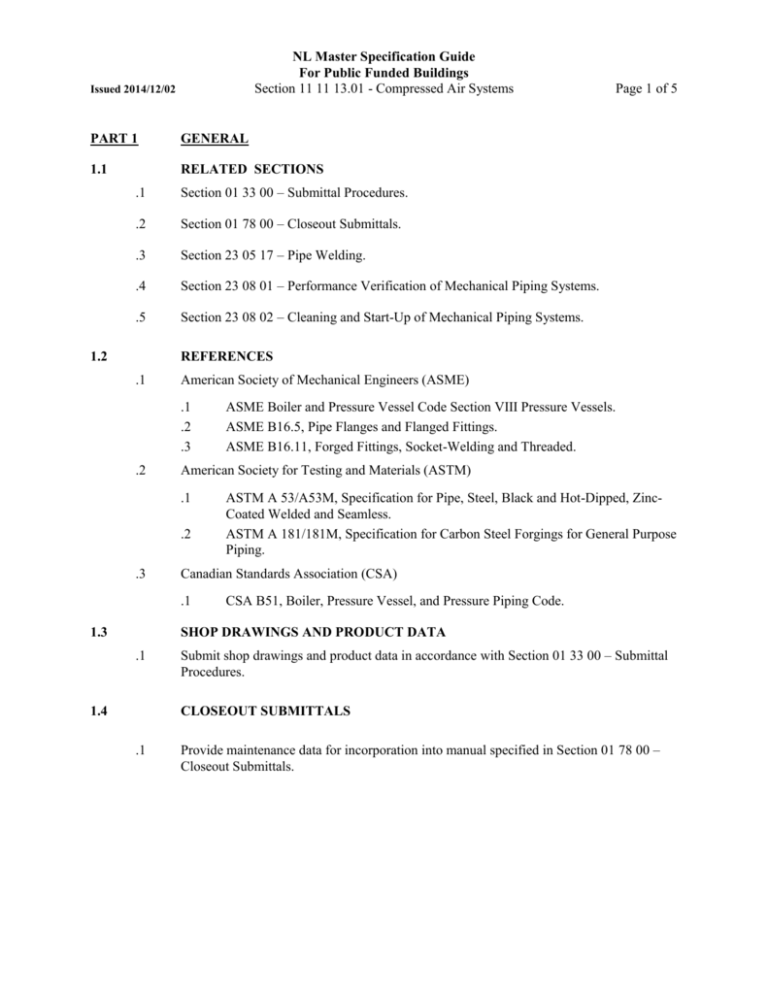
NL Master Specification Guide For Public Funded Buildings Section 11 11 13.01 - Compressed Air Systems Issued 2014/12/02 PART 1 GENERAL 1.1 RELATED SECTIONS .1 Section 01 33 00 – Submittal Procedures. .2 Section 01 78 00 – Closeout Submittals. .3 Section 23 05 17 – Pipe Welding. .4 Section 23 08 01 – Performance Verification of Mechanical Piping Systems. .5 Section 23 08 02 – Cleaning and Start-Up of Mechanical Piping Systems. 1.2 Page 1 of 5 REFERENCES .1 American Society of Mechanical Engineers (ASME) .1 .2 .3 .2 American Society for Testing and Materials (ASTM) .1 .2 .3 ASTM A 53/A53M, Specification for Pipe, Steel, Black and Hot-Dipped, ZincCoated Welded and Seamless. ASTM A 181/181M, Specification for Carbon Steel Forgings for General Purpose Piping. Canadian Standards Association (CSA) .1 1.3 ASME Boiler and Pressure Vessel Code Section VIII Pressure Vessels. ASME B16.5, Pipe Flanges and Flanged Fittings. ASME B16.11, Forged Fittings, Socket-Welding and Threaded. CSA B51, Boiler, Pressure Vessel, and Pressure Piping Code. SHOP DRAWINGS AND PRODUCT DATA .1 1.4 Submit shop drawings and product data in accordance with Section 01 33 00 – Submittal Procedures. CLOSEOUT SUBMITTALS .1 Provide maintenance data for incorporation into manual specified in Section 01 78 00 – Closeout Submittals. NL Master Specification Guide For Public Funded Buildings Issued 2014/12/02 Section 11 11 13.01 - Compressed Air Systems PART 2 PRODUCTS 2.1 Page 2 of 5 AIR COMPRESSOR .1 General: .1 .2 .3 .4 .5 .6 .7 .8 .9 .10 .11 .12 .13 .14 .15 .16 .17 .2 Frame: 100% cast iron frame. Cylinders bolt directly to the cast iron frame. Frame is completely sealed yet allows for maximum accessibility. Crankshaft: Overhung design supported by two heavy duty ball bearings with replaceable crankpin bushing. Entire shaft is balanced with an integral counterweight to ensure smooth operation. Connecting rods: Solid one-piece design. Crankpin bushing inside the rod is precision ground requiring no alignment. Cylinders: 100% cast iron, separately cast and individually bolted to the frame in a V-type configuration. Radial fins on the cylinders help remove heat and ensure 360 degree cooling of the cylinders. Pistons: Precision balanced low pressure aluminum and high pressure cast iron pistons provide smooth operation. Rings: There are four piston rings for sealing compression and oil control. Flywheel: The cast iron fan type flywheel forces a “cyclone” air blast to provide cooling for the deep finned cylinders and multi-finned copper tub intercooler. The flywheel is balanced to keep vibration to a minimum. Intercooler: Two stage compressors use an intercooler. The intercooler between stages is of finned copper tube construction to provide maximum cooling area. The intercooler is provided with a relief valve to prevent over-pressurization. Lubrication: Splash lubrication of running parts is simple and reliable. Lubrication dippers are integral with connecting rods and cannot come loose. Inlet filter: The filter has a durable canister with a dry type 10 micron inlet filter/silencer. Valves: Inlet valves consist of finger valves which allow maximum air flow. Discharge valves are large bore ring valves. Valve plate is easily removed for maintenance. Oil Sight Glass: Indicates visible oil levels at all times. Base: The compressor and motor are aligned on a heavy steel base. Receiver: Receiver mounted units are ASME, National Board coded, and include pressure gauge, drain valve, service valve and relief valve. Drive: The drive is V-belt type with provision for easy adjustment of belt slack. An easily removed, totally enclosed beltguard is standard equipment. Motor: 11.9 kW, 600/3/60 AC motors are 1800 rpm NEMA T frame with dripproof enclosure, Class B insulation, 1.15 Service Factor, and grease lubricated ball bearings. Standard three phase motor voltages are 200, 230/460 and 575. Controls: Automatic start and stop operation with NEMA 1 unloading pressure switch. Automatic start/stop with unloading pressure switch. 15 HP Simplex “Value Fully Packaged” E-Series starter, mounted and wired, in a NEMA-1 enclosure. These packages also include an air-cooled aftercooler which removes up to 70% of the moisture in the NL Master Specification Guide For Public Funded Buildings Issued 2014/12/02 Section 11 11 13.01 - Compressed Air Systems Page 3 of 5 compressed air. Package features a totally enclosed belt guard, belt guard mounted aircooled aftercooler, with electric (115-volt) automatic tank drain. Install kit and start-up kit. U.L. and CSA approved. 2.2 PIPING .1 Piping to ASTM A 53/A53M, schedule 80 seamless black steel. .2 Fittings: .1 .2 NPS2 and smaller: to ASME B16.11, schedule 80 steel, socket welded. NPS2 ½ and larger: to ASME B16.11, schedule 80 steel, butt or socket welded. .3 Couplings: to ASME B16.11, socket welded or threaded half coupling type. .4 Unions: 1000 kPa malleable iron with brass-to-iron ground seat. .5 Dissimiliar metal junctions: use dielectric unions. .6 Flanges: .1 .2 .7 Joints: .1 .2 2.3 NPS2 and smaller: to ASME B16.5, forged steel, raised face and socket welded. NPS2 ½ and larger: to ASME B16.5, forged steel, raised face and slip-on or weld neck. NPS2 and smaller: socket welded. NPS2 ½ and larger: butt welded. BALL VALVES .1 Three piece design or top entry for ease of in-line maintenance. .1 .2 2.4 To ASTM A 181/A181M, Class 70, carbon steel body socket welded or screwed ends, carbon steel ball and associated trim suitable for compressed air application. To withstand 1034 kPa maximum pressure. COUPLERS/CONNECTORS .1 Industrial interchange series, full-bore. .2 Maximum inlet pressure: 1700 kPa. .3 Valve seat: moulded nylon. .4 Body: zinc plated steel. .5 Threads: NPT .6 Acceptable material: Aro, Camlock, Gilbarco. NL Master Specification Guide For Public Funded Buildings Issued 2014/12/02 Section 11 11 13.01 - Compressed Air Systems 2.5 COMBINATION FILTER-REGULATOR-LUBRICATOR GAUGE .1 General: .1 .2 .3 .4 .5 .6 .2 13 mm filter-regulator-lubricator. 1205 kPa max. 51.9 L/s max. 40 micron. 17 ml bowl size. Ingersoll Rand Model C 241-810 Acceptable material: Atlas, Ingersoll Rand, Colman PART 3 EXECUTION 3.1 COMPRESSOR STATION .1 3.2 Page 4 of 5 Install on vibration isolators on housekeeping pad as indicated. COMPRESSED AIR LINE FILTER .1 3.3 Install on discharge line from refrigerated air dryer. MAIN AIR PRESSURE REGULATORS .1 Install at air compressor station. .2 Install additional regulators on connections to equipment as indicated. 3.4 COMPRESSED AIR PIPING CONNECTIONS AND INSTALLATION .1 Install flexible connection in accordance with Section 23 05 16 – Expansion Fittings and Loops for HVAC Piping. .2 Install shut-off valves at outlets, major branch lines and elsewhere where indicated. .3 Install quick-coupler chucks and pressure gauges on drop pipes. .4 Install unions to permit removal or replacement of equipment. .5 Install tees in lieu of elbows at changes in direction of piping. Install plug in open ends of tees. .6 Grade piping at 1% slope minimum. .7 Install compressed air trap and pressure equalizing pipe at moisture collecting points. Drain pipe to nearest floor drain. .8 Make branch connections from top of main. NL Master Specification Guide For Public Funded Buildings Issued 2014/12/02 Section 11 11 13.01 - Compressed Air Systems Page 5 of 5 .9 Install compressed air trap at bottom of risers and at low points in mains, piped to nearest drain. Distance between drain points to be 30 m maximum. .10 Cleaning: .1 .11 Testing: .1 3.5 Blow out piping to clean interior thoroughly of oil and foreign matter. Pressure test for 4 h minimum, to 1100 kPa, with outlets closed and with compressor isolated from system. Pressure drop not to exceed 10 kPa. START-UP AND PERFORMANCE VERIFICATION .1 Refer to Section 23 08 02 – Cleaning and Start-Up of Mechanical Piping System and Section 23 08 01 – Performance Verification of Mechanical Piping System. END OF SECTION


