Chamonix_2012_Verweij - Indico
advertisement
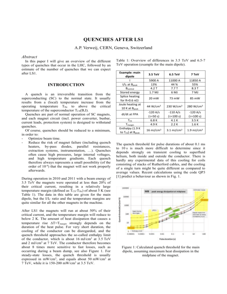
QUENCHES AFTER LS1 A.P. Verweij, CERN, Geneva, Switzerland Abstract In this paper I will give an overview of the different types of quenches that occur in the LHC, followed by an estimate of the number of quenches that we can expect after LS1. INTRODUCTION A quench is an irreversible transition from the superconducting (SC) to the normal state. It usually results from a (local) temperature increase from the operating temperature THe to above the critical temperature of the superconductor TCS(B,I). Quenches are part of normal operation of SC magnets, and each magnet circuit (incl. power converter, busbar, current leads, protection system) is designed to withstand quenches. Of course, quenches should be reduced to a minimum, in order to: - Optimize beam time. - Reduce the risk of magnet failure (including quench heaters, by-pass diodes, parallel resistances, extraction systems, instrumentation, …). Quenches often cause high pressures, large internal voltages, and high temperature gradients. Each quench therefore always represents a small possibility (of the order of 10-4) that the magnet will not work properly afterwards. During operation in 2010 and 2011 with a beam energy of 3.5 TeV the magnets were operated at less than 20% of their critical current, resulting in a relatively large temperature margin (defined as TCS-THe) of about 5 K (see Table 1). The data in this table are given for the main dipole, but the I/IC ratio and the temperature margins are quite similar for all the other magnets in the machine. After LS1 the magnets will run at about 50% of their critical current, and the temperature margin will reduce to below 2 K. The amount of heat dissipation that causes a temperature rise T=Tmargin strongly depends on the duration of the heat pulse. For very short duration, the cooling of the conductor can be disregarded, and the quench threshold approaches the so-called enthalpy limit of the conductor, which is about 16 mJ/cm3 at 3.5 TeV and 2 mJ/cm3 at 7 TeV. The conductor therefore becomes about 8 times more sensitive to fast losses, such as occurring during a beam dump, see also Figure 1. For steady-state losses, the quench threshold is usually expressed in mW/cm3, and equals about 50 mW/cm3 at 7 TeV, while it is 150-200 mW/cm3 at 3.5 TeV. Table 1: Overview of differences in 3.5 TeV and 6.5-7 TeV operation (example for the main dipole). Example: main dipole I I/IC at Bpeak Bcentral Stored energy Splice heating for R=0.6 n Joule heating at 10 K at Bpeak dI/dt at FPA TCS Tmargin Enthalpy (1.9 K to TCS) at Bpeak 3.5 TeV 6.5 TeV 7 TeV 5900 A 13% 4.2 T 1.7 MJ 11000 A 44 % 7.7 T 6 MJ 11850 A 55% 8.3 T 7 MJ 20 mW 73 mW 85 mW 44 W/cm3 230 W/cm3 280 W/cm3 -120 A/s (=50 s) 6.8 K 4.9 K -110 A/s (=100 s) 4.1 K 2.2 K -120 A/s (=100 s) 3.5 K 1.6 K 16 mJ/cm3 3.1 mJ/cm3 1.9 mJ/cm3 The quench threshold for pulse durations of about 0.1 ms to 10 s is much more difficult to determine since it depends strongly on transient cooling to superfluid helium, both inside and outside the conductor. There is hardly any experimental data of this cooling for coils consisting of stacks of Rutherford cables, and the cooling of a single turn might be quite different as compared to average values. Recent calculations using the code QP3 [1] predict a behaviour as shown in Fig. 1. Figure 1: Calculated quench threshold for the main dipole, assuming maximum heat dissipation in the midplane of the magnet. TYPE OF QUENCHES It is convenient to distinguish 4 types of quenches, as shown in Figure 2. Quenches triggering a FPA (so numbers 1 and 3) have of course a larger impact on operation, since they also cause a beam dump. Quenches happening after a FPA have less impact but should be avoided as much as possible, especially in large-size magnets, to reduce the cryogenic recuperation time and to minimize the stress variations inside the magnets. These 4 types of quenches will be discussed in the following subsections. Figure 2: Overview of the 4 types of quenches. 1. Quenches triggering a FPA & beam dump These quenches are caused by: • Local resistive heating, especially in a splice internal to the magnet coil, or in the SC if there are local defects. Such quenches are very reproducible, and (if present) already observed during the magnet reception tests, and are therefore not expected after LS1. However, parts of the coil exhibiting local heating, operate at T He<T<TCS, and are hence more ‘sensitive’ to beam losses. • Non-uniform transport current, caused by a nonuniform joint resistance, and by ramping the magnet. Such quenches can only occur in magnets wound from multi-strand cables, i.e. MB, MQ, IPQ, IPD, IT. The non-uniformity diffuses slowly through the cable (order of 1-10 m/hr), and are therefore not observed at magnet reception tests. Quenches are not expected at low dI/dt (1-10 A/s) or high negative dI/dt. However, strands carrying more than the average transport current will become more ‘sensitive’ to beam losses, since their temperature margin is smaller. • Conductor movement. Quenches of this type are often referred to as training quenches (or natural quenches). The training will be dominated by the main dipoles. The (surprising) statistics from the HWC in May/June 2008 in S56 can be used to estimate the number of training quenches after LS1 (see [2],[3],[4]). Training quenches can be done just after LS1 during a HWC campaign with 2-3 quenches per day and per sector, and several sectors in parallel. I would personally limit the number of RB quenches (just after LS1) to about 50-100, so as to operate at about 6.5 TeV beam energy, and possibly push further towards 7 TeV a few years later. It cannot be excluded that 4 years of additional powering, relaxation, and thermal cycling have another non-expected effect on the training. All other circuits will be trained to nominal before LS1 (see [5]), and training after LS1 (i.e. after a long thermal cycle) will probably be rather quick. Large de-training is not frequently observed, and training quenches during beam operation will therefore be rare (but requires that the operating current is several % below the training current). • Beam loss. Beam induced quenches can be avoided by setting the BLM thresholds below the calculated quench threshold (of course after scaling and conversion from mJ/cm3 to Gy/s), except for some losses with a duration less than about 0.3 ms (i.e. the time needed for detection+dump). Unfortunately, due to unknown loss type, loss origin, and inaccuracies in the calculation of the energy deposition (using Fluka), and the quench threshold (using QP3), the BLM threshold has to be set at a very conservative value if one wants to be sure to avoid all beam induced quenches. Until LS1 (knowing that we have defective 13 kA joints) conservative setting is recommendable in order to minimize the probability of main dipole quenches, eventually propagating towards a defective joint. After LS1, the BLM thresholds should be set so as to optimize the stable beams time, of course without putting in danger the safety of the magnets. There is no need to avoid all quenches. Avoiding 80-90% seems a good target. However, 100% should be targeted for magnets for which there are no spares. 2. Quenches that are caused by a FPA Two sequences can be distinguished: • AC losses resulting from the high dI/dt (and dB/dt). In many corrector magnets these AC losses cause a temperature rise above TCS and quench the magnet, see for example Figure 3. This should however not happen in the main dipoles at 12 kA, RB=100 s, and main quads at 12 kA, RQ=30 s. • Heat propagation from an adjacently quenched magnet. This propagation almost always occurs from a quenched dipole to several other dipoles, but is very unlikely from dipole to quadrupole or from quadrupole to dipole, and never occurs for all other magnets. quenches will mainly depend on the energy level at which one would like to operate after LS1. Roughly 100 quenches can be expected for the MB’s and a few for the MQ’s for operation at 6.5 TeV per beam. For 6 TeV these numbers will be roughly 10x smaller, while for 7 TeV they will be 10x larger (with a large uncertainty), see also [2],[4]. 2. Quenches that are caused by a FPA Each training quench in the MB’s will propagate to several adjacent MB’s. So 100 training quenches will cause heater firing in about 400-500 MB’s. Furthermore, during heat run tests, there will be a quenchback of many corrector magnets. Figure 3: Current in the corrector circuit RQTL9. The MQTL magnet quenches 0.2 s after the FPA. 3. Quenches that result from false triggering of the QPS, and that subsequently trigger a FPA and dump the beam Noise, caused by thunderstorms, radiation, glitches, etc. can cause false triggering of the QPS, which in turn fires the quench heaters, hence quenching the magnet. Of course, this can only occur in magnets equipped with quench heaters. Alternatively, it is also possible that such noise causes a false triggering of a quench heater power supply, hence quenching the magnet. The sensitivity of the QPS system increases for smaller thresholds, shorter discrimination times, and longer distance between the voltage taps. Sensitive circuits should be improved during LS1, basically by segmenting the protection. 4. Quenches that are caused by false triggering of the QPS, resulting from a FPA. False triggering can be due to: • Inductive voltages caused by the FPA in a mutuallycoupled circuit. Especially nested magnets are very susceptible. This should be observed during HWC, and can be reduced (if needed) by increasing QPS thresholds, or by increasing decay time constants. • An imbalance in the QPS detection bridge. Also in this case, the triggering can be avoided by fine-tuning the bridge, or by increasing QPS thresholds or decay time constants. QUENCHES DURING HWC AFTER LS1 1. Quenches triggering a FPA & beam dump. Except for the 13 kA circuits, all magnets will be trained at the start of LS1. An estimation of the expected number of quenches is given in [4]. Retraining of these magnets after LS1 will be rather fast. The training of the 13 kA circuits can only be done after LS1, once the interconnects are consolidated. The number of training 3. Quenches that result from false triggering of the QPS, and that subsequently trigger a FPA and dump the beam None or very few. 4. Quenches that are caused by false triggering of the QPS, resulting from a FPA. There will initially be some, but these will be solved by fine-tuning the QPS. QUENCHES AFTER LS1 1. Quenches triggering a FPA & beam dump. There will be some de-training quenches. The number depends strongly on the operating current as compared to the maximum obtained current during HWC. There will furthermore be several beam-induced quenches, possibly dominated by UFO’s (see [6]). These cannot be avoided because the BLM setting should be less conservative than present values, in order to reduce the number of beam dumps that were not needed. 2. Quenches that are caused by a FPA There will be some quenches in MB’s due to heat propagation from adjacently quenching MB’s, and regular quench back in many corrector magnets. 3. Quenches that result from false triggering of the QPS, and that subsequently trigger a FPA and dump the beam There will be a few per year, rarely in the 13 kA circuits. Most of them will be due to radiation-induced false triggering. Solutions to reduce false triggering are discussed in [7]. 4. Quenches that are caused by false triggering of the QPS, resulting from a FPA. There will probably be only a few, and mainly in the corrector circuits. CONCLUSION REFERENCES Beam-induced quenches and false triggering of the QPS will be the main cause of those quenches that cause a beam dump. Possibly in total up to 10-20 per year. After consolidation of the 13 kA joints, the approach for the BLM settings can be less conservative than in 2010-2012 in order to maximize beam time. This will cause some quenches but, anyhow, a beam–induced quench is not more risky than a quench provoked by false triggering. It is not easy to predict the number of BLM triggered beam dumps, needed to avoid magnet quenches, because it is not sure how to scale beam losses and UFO’s from 3.5 TeV to 6.5 TeV, and it is not sure if the thresholds at 3.5 TeV are correct. Quench events will be much more massive (ex: RB quench at 6 kA 2 MJ, RB quench at 11 kA 6-20 MJ), and as a result cryo recuperation much longer. There will also be more ramp induced quenches after a FPA in other circuits due to higher ramp rates and smaller temperature margins (mutual coupling). [1] A.P. Verweij, “QP3, Users manual”, EDMS 1150045 (2011) [2] A.P. Verweij, “Training the dipoles”, Proceedings Chamonix 2009 workshop, pp. 25-28 (2009) [3] B. Bellesia, N. Catalan Lasheras, E. Todesco, “Magnet (re)training, Proceedings Chamonix 2009 workshop, pp. 264-270 (2009). [4] E. Todesco, C. Lorin, M. Bajko, “Energy of the LHC after the 2013-2014 shutdown”, these proceedings (2012). [5] M. Pojer, ”Powering tests before LHC warm-up: What is new from Chamonix 2011?”, these proceedings (2012). [6] T. Baer, “UFOs in the LHC after LS1”, these proceedings (2012). [7] R. Denz, “QPS upgrade and machine protection during LS1”, these proceedings (2012).
