A01, Sizing Procedures
advertisement

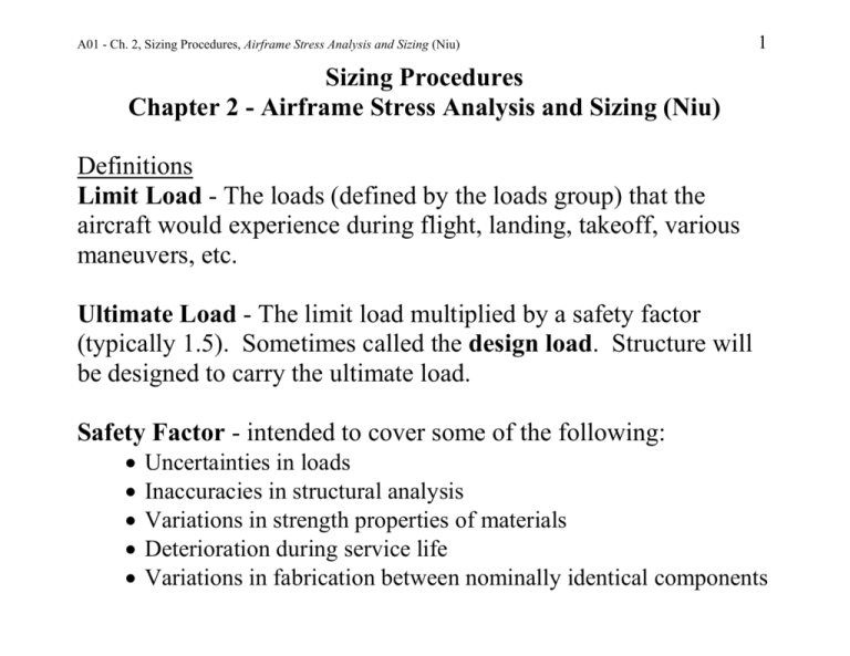
A01 - Ch. 2, Sizing Procedures, Airframe Stress Analysis and Sizing (Niu) 1 Sizing Procedures Chapter 2 - Airframe Stress Analysis and Sizing (Niu) Definitions Limit Load - The loads (defined by the loads group) that the aircraft would experience during flight, landing, takeoff, various maneuvers, etc. Ultimate Load - The limit load multiplied by a safety factor (typically 1.5). Sometimes called the design load. Structure will be designed to carry the ultimate load. Safety Factor - intended to cover some of the following: Uncertainties in loads Inaccuracies in structural analysis Variations in strength properties of materials Deterioration during service life Variations in fabrication between nominally identical components A01 - Ch. 2, Sizing Procedures, Airframe Stress Analysis and Sizing (Niu) Preliminary Sizing Preliminary Sizing Calculations: Provide data to begin project Take 6 months to one year Require the most experienced engineers Based on given conditions and loads Use rough or approximation methods of calculation to obtain quick answers Require knowledge of fatigue and damage tolerant design Stress check usually not required Require basic knowledge of Material selection Manufacturing and fabrication costs Repairability, maintainability and assembly procedures Future aircraft growth considerations 2 A01 - Ch. 2, Sizing Procedures, Airframe Stress Analysis and Sizing (Niu) 3 Production Stress Analysis Production stress work: Takes about two years to complete (commercial transports) Consists of detailed stress analysis Based on given structure, materials, loads, etc. Requires knowledge of methods of stress analysis: from airframe company's design manuals other sources Requires use of computers and FEM for more accurate analysis Defines Margin of Safety (MS) under static loads (ultimate load conditions) want to keep MS close or near to 0 to save structural weight allow high MS only for special requirements such as fatigue, stiffness requirements, test results that indicate analysis may be in error, etc. A01 - Ch. 2, Sizing Procedures, Airframe Stress Analysis and Sizing (Niu) 4 Margin of Safety (MS) Recall: Limit load = load that the structure will experience Ultimate load = safety factor X limit load Structure must be able to support limit loads without detrimental permanent deformation. Margin of Safety (MS) under the ultimate load condition is defined by allowable ( xx) MS( xx ) 1 ultimate ( xx) where: (xx)= critical condition such as tensile stress, compressive stress, shear stress, bending moment, bearing stress, tensile yield stress, vonMises stress, etc. A01 - Ch. 2, Sizing Procedures, Airframe Stress Analysis and Sizing (Niu) Typically, a MS that is based on ultimate static strength will be used unless it is overridden by the following criteria: Adequate fatigue life for the loading spectrums Sufficient rigidity for the aero-elastic or dynamic considerations Damage tolerance Remember, a structural design with several margins greater then zero may be over-designed. Therefore is may be quite safe, but will have higher weight, more costly to operate, carry less payload, etc. On the other hand, with all margins close to zero AND a small safety factor (typical of advanced military applications), failures may occasionally be expected. 5 A01 - Ch. 2, Sizing Procedures, Airframe Stress Analysis and Sizing (Niu) 6 Stiffness Requirements Aircraft are typically designed to be flexible. However, in some instances, service failure and malfunction of various mechanical devices may occur due to insufficient rigidity or improper allowance for possible and/or probably build-up of material and manufacturing tolerances, i.e., Loss of doors, access panels, etc., and/or improper seating of doors due to excessive deflections and adverse tolerance buildup. Loss of canopies due to adverse tolerances and excessive deflection. Specifications will require that all devices maintain full strength and function properly under deflections and stresses at limit loads. You (the Stress Group) are responsible for sufficient system rigidity that affects tolerances, seating, mating of components, sealing of enclosures, etc. A01 - Ch. 2, Sizing Procedures, Airframe Stress Analysis and Sizing (Niu) 7 The Structural Dynamics Group often specifies rigidity requirements for various items: The Stress Group is responsible for sufficient control system rigidity and the effect of tolerances, where applicable, should be considered when calculating the rigidity of control systems. Consideration should be given to the effects of limit deflections on the device whether due to limit load on the device or due to limit load on other parts of the airplane. In addition to the specification requirements, the Structural Dynamics department often specifies rigidity requirements for various items: Requires structural stiffness of EI (bending stiffness) and GJ (torsional stiffness) values for wing empennage and engine pylon for divergence to prevent flutter in high speed flight GJ values for control surface structures A01 - Ch. 2, Sizing Procedures, Airframe Stress Analysis and Sizing (Niu) 8 In Summary Practical stress analysis and sizing can be outlined as following: Practically, stress analysis is not an exact solution but is a good approximation and its derivation is covered by the safety factor of 1.5 (or whatever value is chosen). Conventional methods of stress (or structural) analysis obtained from college study, textbooks, handbooks of structural formulas or equations, etc. that mostly cannot be directly used on airframe sizing because there are many effects from various boundary conditions, elastic supports, loading conditions, etc. The input of engineering judgment and/or assumption is frequently to be used to modify the conventional method of analysis to fit the need. A01 - Ch. 2, Sizing Procedures, Airframe Stress Analysis and Sizing (Niu) 9 Sometimes structural tests may be required to justify or modify the conventional method of analysis for critical components, e.g., cutouts, critical joint analysis, etc. Boeing is using a “virtual manufacturing and assembly” process on the production planning and assembly simulation of the 787 Dreamliner. Utilizes the DELMIA, CATIA, and ENOVIA software packages. The best computer is "you" not the computerized method which is merely a very good too] for your use to gain calculation speed and to solve highly redundant structural systems Engineers shall understand what is in the computer analysis rather than just perform the input and output process; otherwise it makes no difference between "you" and a robot (so called "engineering crisis" which will end up to be a Murphy's Law result!). A01 - Ch. 2, Sizing Procedures, Airframe Stress Analysis and Sizing (Niu) Traditionally, when in "doubt", the engineer uses a conservative method or approach to size airframe structures and the level of conservatism is based upon engineering judgment 10


