Solution - Solar Physics Group
– 1 –
Solution to HW Problems
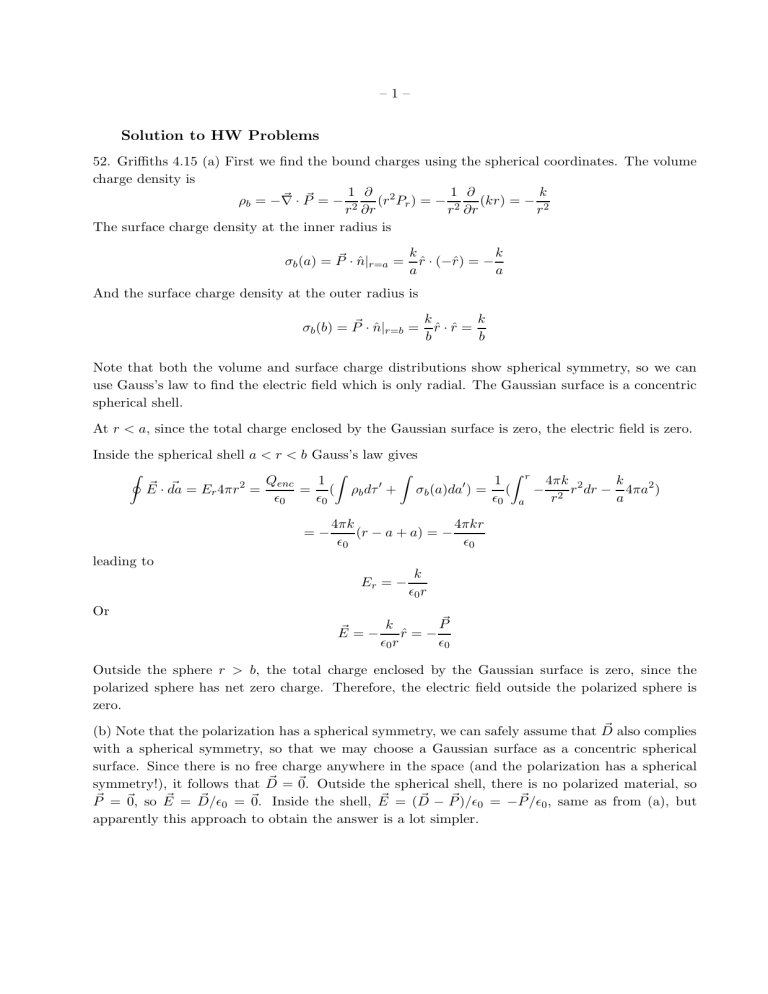
52. Griffiths 4.15 (a) First we find the bound charges using the spherical coordinates. The volume charge density is
ρ b
= −
~ ~
= −
1 r 2
∂
∂r
( r 2 P r
) = − r
1
2
∂
∂r
( kr ) = − k r 2
The surface charge density at the inner radius is
σ b
( a ) =
~
· ˆ | r = a
= k a
ˆ · ( − r ) = − k a
And the surface charge density at the outer radius is
σ b
( b ) =
~
· ˆ | r = b
= k
ˆ · r = b k b
Note that both the volume and surface charge distributions show spherical symmetry, so we can use Gauss’s law to find the electric field which is only radial. The Gaussian surface is a concentric spherical shell.
At r < a , since the total charge enclosed by the Gaussian surface is zero, the electric field is zero.
Inside the spherical shell a < r < b Gauss’s law gives
I
~
·
~
= E r
4 πr 2 =
Q enc ǫ
0
=
1 ǫ
0
(
Z
ρ b dτ ′ +
Z
σ b
( a ) da ′ ) =
1 ǫ
0
(
Z a r
−
4 πk r 2 r 2 dr − k a
4 πa 2 )
= −
4 πk ǫ
0
( r − a + a ) = −
4 πkr ǫ
0 leading to
E r k
= − ǫ
0 r
Or
~
= − k ǫ
0 r
ˆ = − ǫ
0
Outside the sphere r > b , the total charge enclosed by the Gaussian surface is zero, since the polarized sphere has net zero charge. Therefore, the electric field outside the polarized sphere is zero.
(b) Note that the polarization has a spherical symmetry, we can safely assume that
~ also complies with a spherical symmetry, so that we may choose a Gaussian surface as a concentric spherical surface. Since there is no free charge anywhere in the space (and the polarization has a spherical symmetry!), it follows that
~
=
~
=
~
=
~
0
=
~
= (
~
−
~
) /ǫ
0
= −
~
0
, same as from (a), but apparently this approach to obtain the answer is a lot simpler.
– 2 –
53. Griffiths 4.18 (a) The displacement field does not feel the material and is determined by the free charge. In this setup, the displacement between two charge surface is
~
= − σ z .
(b) The electric field in the linear dielectric material is given by slab,
~
= − σ/ (2 ǫ
0 z , and in the lower half of the slab,
~
= − σ/
~
(1 .
=
5 ǫ
0
~
)ˆ
. In the upper half of the
= − 2 σ/ (3 ǫ
0
)ˆ .
(c) For the linear material, in the lower half,
~
= ǫ
0
χ ~ = ǫ
0
( ǫ r
~
= ǫ
0
(1 .
5 − 1)
~
= − σ/ z .
− 1)
(d) The potential difference is given by V = −
R
2 σa/ (3 ǫ
0
) + σa/ (2 ǫ
0
) = 7 σa/ (6 ǫ
0
).
~
. In the upper half,
~
·
~
= −
R
0
− a
~
= ǫ
0
(2
− 2 σ/ (3 ǫ
0
) dz −
R
−
0 a
1)
−
~
= − σ/ z ;
σ/ (2 ǫ
0
) dz =
(e) The polarization in each half slab is constant, so the volume bound charge is zero. The surface bound charge is given by
~
· n . Here we consider 3 surfaces, the top surface, the boundary between the two dielectric materials, and the bottom surface. At the top surface, ˆ z ; at the bottom surface, ˆ = − ˆ , and at the boundary between the two materials, ˆ = − z for the upper half, and
ˆ z for the lower half. Therefore, we find the surface bound charge at the top, middle boundary, and bottom surfaces as σ b
= − σ/ 2 , σ/ 6(= σ/ 2 − σ/ 3) , σ/ 3, respectively. It can be easily seen that the total bound charge is zero, as should be.
(f) From (e), we can compute all the surface charges at the top, middle, and bottom surface to be: σ tot
= σ/ 2 , σ/ 6 , − 2 σ/ 3, respectively. All these surface charges generate the net electric field between the two plates. Recall that a uniform surface charge generates a uniform electric field as E = ± σ/ (2 ǫ
0
) above (+) and below (-) the surface, respectively. The electric field by this configuration is a superposition of contribution by all 3 surfaces. In the upper half of the slab, the net electric field is
E z
= −
σ/ 2
2 ǫ
0
+
σ/ 6
2 ǫ
0
+
− 2 σ/ 3
2 ǫ
0
σ
= −
2 ǫ
0
In the lower half of the slab, the net electric field is
E z
= −
σ/ 2
2 ǫ
0
−
σ/ 6
2 ǫ
0
+
− 2 σ/ 3
2 ǫ
0
2 σ
= −
3 ǫ
0
The result is the same as obtained in (b).
54. Griffiths 4.21 In the configuration, if an amount of charge λ per unit length is carries by the copper cable, and charge − λ is distributed at the outer surface, then we can find the electric field and the potential difference V between the inner and outer radius. In this configuration, we first find the displacement field using Gauss’s law, and the Gaussian surface is a coaxial cylidrical shell of radius s . At s < a and s > c , the total enclosed free charge is zero and the polarization is zero
(no dielectric material), so
~
=
~
=
~
0
=
At a < s < b , using Gauss’s law, we find
~
= 2 πλ s
ˆ , and
~
=
~
0
= 2 πλ ǫ
0 s
ˆ .
At b < s < c , in the same way, we get
~
= 2 πλ s
ˆ , but
~
=
~
= 2 πλ ǫs
ˆ , where ǫ = ǫ
0 ǫ r
.
– 3 –
The potential difference between the inner and outer surfaces is therefore
V = −
Z s = a s = c
~
·
~
= −
Z s = b s = c
2 πλ ds − ǫs
Z s = a s = b
2 πλ ǫ
0 s
=
2 πλ ǫ
0
1
[ ǫ r ln ( c/b ) + ln ( b/a )]
The capacitance per unit length of the cable is therefore
C =
λ
V
=
2 πǫ r ǫ
0 ln ( c/b ) + ǫ r ln ( b/a )
55. Griffiths 4.19 Suppose the distance between the two plates is d , and the area of the plates is
A . A given potential difference V between the two plates without dielectric material in between is given by V = σd/ǫ
0
, and the capacitance is C
0
= Q/V = σA/V = Aǫ
0
/d .
For the first case in the problem, suppose that the top and bottom surfaces have free charge density ± σ f
, the displacement field is the same in the gaps and in the material, D = σ f
, pointing from the top to the bottom. The electric field is therefore E = D/ǫ
0
= σ f
/ǫ
0 in the gaps, and
E = D/ǫ = σ f
/ǫ in the material, where ǫ = ǫ
0 ǫ r negative charge (bottom). The potential difference between the two plates is V = −
~
·
~
=
σ f d/ (2 ǫ
0
) + σ f d/ (2 ǫ ) = σ f d/ (2 ǫ
0
)(1 + 1 /ǫ r
). The capacitance is therefore
C
1
=
Q
V
=
σ f
A
V
=
Aǫ
0 d
2 ǫ r
1 + ǫ r
= C
0
2 ǫ r
1 + ǫ r
For the second case, to maintain the potential difference V , the left half of the capacitor will have to carry more free charges than the right half of the capacitor to compensate for the bound charges due to polarization of the dielectric material. To have the same V , in both halves, E = V /d . In the left half, D = σ l
= ǫE leading to
The capacitance is therefore
σ l
= ǫV /d . In the right half, D = σ r
= ǫ
0
E leading to σ r
= ǫ
0
V /d .
C
2
=
Q
V
=
A
2
σ l
+
V
A
2
σ r
=
Aǫ
0 ǫ r
+ 1 d 2
= C
0 ǫ r
+ 1
2
It can be easily seen that C
1
− C
2
< 0, so C
1
< C
2
.
In the first case, the free charge density at the top or bottom is given as
σ f
=
V ǫ
0 d
2 ǫ r ǫ r
+ 1
We can take the positive charge at the top and the negative charge at the bottom. In the dielectric material,
P = D ǫ r
− ǫ r
1
=
V ǫ
0
2( ǫ r
− 1) d ǫ r
+ 1
– 4 –
And
σ b
= P =
V ǫ
0
2( ǫ r
− 1) d ǫ r
+ 1
The negative bound charge is at the top of the material.
In the second case, in the left, the free charge is given by
σ l
= ǫ r ǫ
0
V d and in the right, the free charge is
σ r
= ǫ
0
V d
The polarization in the left is
P = D ǫ r
− ǫ r
1
= ǫV d ǫ r
− 1 ǫ r
= ( ǫ r
− 1) ǫ
0
V d and
σ b
= P = ( ǫ r
− 1) ǫ
0
V d negative at the top and positive at the bottom.

