Lab 7: Basic RIP Configuration
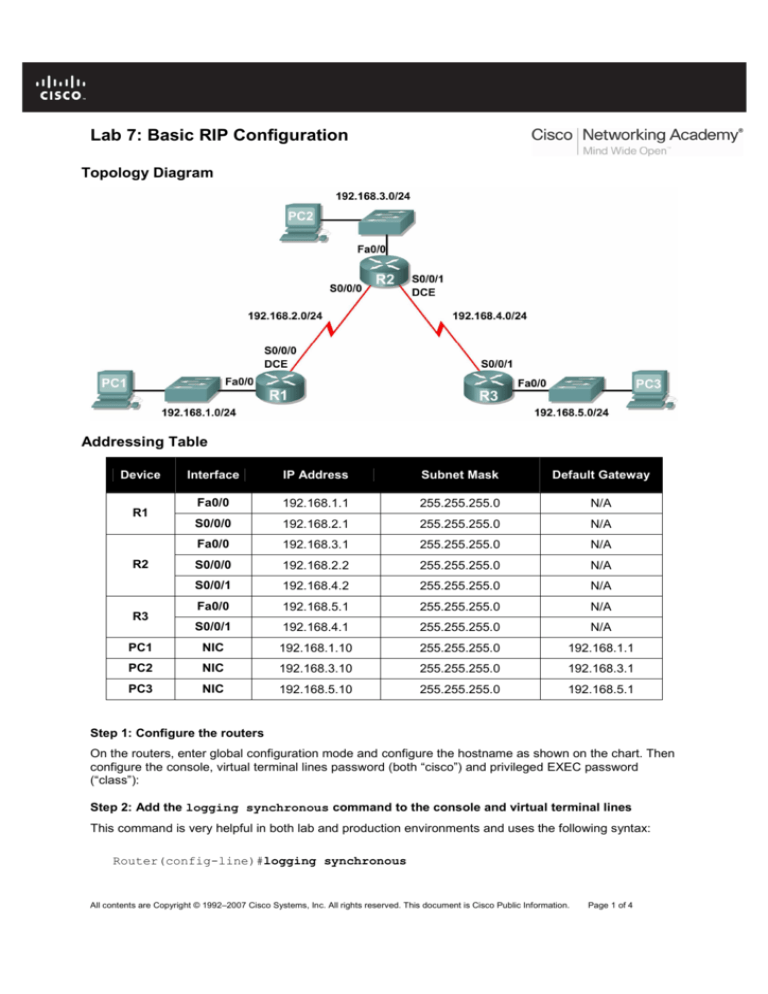
Topology Diagram
Addressing Table
Device
Interface
IP Address
Subnet Mask
Default Gateway
Fa0/0
192.168.1.1
255.255.255.0
N/A
S0/0/0
192.168.2.1
255.255.255.0
N/A
Fa0/0
192.168.3.1
255.255.255.0
N/A
S0/0/0
192.168.2.2
255.255.255.0
N/A
S0/0/1
192.168.4.2
255.255.255.0
N/A
Fa0/0
192.168.5.1
255.255.255.0
N/A
S0/0/1
192.168.4.1
255.255.255.0
N/A
PC1
NIC
192.168.1.10
255.255.255.0
192.168.1.1
PC2
NIC
192.168.3.10
255.255.255.0
192.168.3.1
PC3
NIC
192.168.5.10
255.255.255.0
192.168.5.1
R1
R2
R3
Step 1: Configure the routers
On the routers, enter global configuration mode and configure the hostname as shown on the chart. Then
configure the console, virtual terminal lines password (both “cisco”) and privileged EXEC password
(“class”):
Step 2: Add the logging synchronous command to the console and virtual terminal lines
This command is very helpful in both lab and production environments and uses the following syntax:
Router(config-line)#logging synchronous
All contents are Copyright © 1992–2007 Cisco Systems, Inc. All rights reserved. This document is Cisco Public Information.
Page 1 of 4
CCNA Exploration
Routing Protocols and Concepts: RIP version 1
Lab 7: Basic RIP Configuration
Step 3: Disable DNS lookup
Router(config)#no ip domain-lookup
Step 4: Configure the interfaces on R1, R2, and R3
Configure the interfaces on the R1, R2, and R3 routers with the IP addresses from the table under the
Topology Diagram.
Step 5: Verify IP addressing and interfaces
Use the show ip interface brief command to verify that the IP addressing is correct and that the
interfaces are active.
Step 6: Configure Ethernet interfaces of PC1, PC2, and PC3
Configure the Ethernet interfaces of PC1, PC2, and PC3 with the IP addresses and default gateways
from the table under the Topology Diagram.
Step 7: Test the PC configuration by pinging the default gateway from the PC
Task: Configure RIP
Step 1: Enable dynamic routing
To enable a dynamic routing protocol, enter global configuration mode and use the router command.
Enter router ? at the global configuration prompt to a see a list of available routing protocols on your
router.
To enable RIP, enter the command router rip in global configuration mode.
Router(config)#router rip
Step 2: Enter classful network addresses
Once you are in routing configuration mode, enter the classful network address for each directly
connected network, using the network command with the following syntax:
Router(config-router)#network <network_nr>
Router(config-router)#network <network_nr>
The network command:
•
Enables RIP on all interfaces that belong to this network. These interfaces will now both send and
receive RIP updates.
•
Advertises this network in RIP routing updates sent to other routers every 30 seconds.
Task: Verify RIP Routing
Step 1: Use the show ip route command to verify that each router has all of the networks in the
topology entered in the routing table
Routes learned through RIP are coded with an R in the routing table.
Step 2: Use the show ip protocols command to view information about the routing processes
The show ip protocols command can be used to view information about the routing processes that
are occurring on the router. This output can be used to verify most RIP parameters to confirm that:
All contents are Copyright © 1992–2007 Cisco Systems, Inc. All rights reserved. This document is Cisco Public Information.
Page 2 of 4
CCNA Exploration
Routing Protocols and Concepts: RIP version 1
•
Lab 7: Basic RIP Configuration
RIP routing is configured
•
The correct interfaces send and receive RIP updates
•
The router advertises the correct networks
•
RIP neighbors are sending updates
Step 3: Use the debug ip rip command to view the RIP messages being sent and received
Rip updates are sent every 30 seconds so you may have to wait for debug information to be displayed.
For example:
R1#debug ip rip
R1#RIP: received v1 update from 192.168.2.2 on Serial0/0/0
192.168.3.0 in 1 hops
192.168.4.0 in 1 hops
192.168.5.0 in 2 hops
RIP: sending v1 update to 255.255.255.255 via FastEthernet0/0 (192.168.1.1)
RIP: build update entries
network 192.168.2.0 metric 1
network 192.168.3.0 metric 2
network 192.168.4.0 metric 2
network 192.168.5.0 metric 3
RIP: sending v1 update to 255.255.255.255 via Serial0/0/0 (192.168.2.1)
RIP: build update entries
network 192.168.1.0 metric 1
The debug output shows that R1 receives an update from R2. Notice how this update includes all the
networks that R1 does not already have in its routing table. Because the FastEthernet0/0 interface
belongs to the 192.168.1.0 network configured under RIP, R1 builds an update to send out that interface.
The update includes all networks known to R1 except the network of the interface. Finally, R1 builds an
update to send to R2. Because of split horizon, R1 only includes the 192.168.1.0 network in the update.
Step 4: Discontinue the debug output with the undebug all command
R1#undebug all
All possible debugging has been turned off
Step 5: Show only RIP statements in the routing table
a. Enter show ip route rip command
b. What is the administrative distance of RIP? __________________________
Step 6: Last route update
a.
Check the routing table for a specific route (IOS version must be at least 12.x)
For example: Enter show ip route 192.168.1.0
b. When was the last update? ___________________________________________
c. What is the default update time for RIP? _________________________________
Step 7: Configure your router to stop sending updates out the FastEthernet0/0 interface
Sending updates out this interface wastes the bandwidth and processing resources of all devices on the
LAN. In addition, advertising updates on a broadcast network is a security risk. RIP updates can be
intercepted with packet sniffing software. Routing updates can be modified and sent back to the router,
corrupting the router table with false metrics that misdirects traffic.
The passive-interface fastethernet 0/0 command in routing configuration mode is used to
disable sending RIPv1 updates out that interface.
All contents are Copyright © 1992–2007 Cisco Systems, Inc. All rights reserved. This document is Cisco Public Information.
Page 3 of 4
CCNA Exploration
Routing Protocols and Concepts: RIP version 1
Lab 7: Basic RIP Configuration
Router(config-router)#passive-interface fastethernet 0/0
Step 8: Verify that updates are not sent to interface FastEthernet0/0 anymore
You can use show ip protocols to ensure FastEthernet0/0 is passive. You can also use debug ip
rip to ensure that router is not sending any RIP updates to FastEthernet0/0
Note: Sometimes it is necessary to clear the dynamic routing table. Try the command
Router # clear ip route *
on both R1 and R2 (you can also do it on the R3). This command will cause the routers to immediately
flush routes in the routing table and request updates from each other.
Task: Clean Up
Erase the configurations and disconnect attached cabling
All contents are Copyright © 1992–2007 Cisco Systems, Inc. All rights reserved. This document is Cisco Public Information.
Page 4 of 4

