numerical investigations regarding contact
advertisement

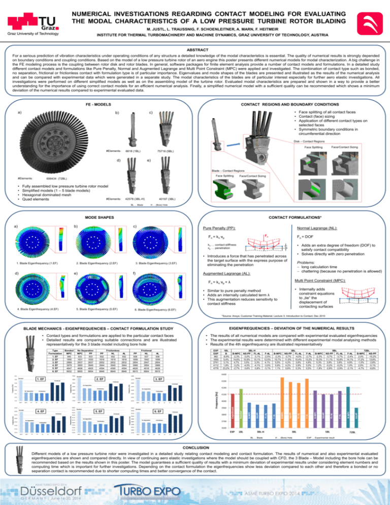
NUMERICAL INVESTIGATIONS REGARDING CONTACT MODELING FOR EVALUATING THE MODAL CHARACTERISTICS OF A LOW PRESSURE TURBINE ROTOR BLADING M. JUSTL, L. TRAUSSNIG, F. SCHOENLEITNER, A. MARN, F. HEITMEIR INSTITUTE FOR THERMAL TURBOMACHINERY AND MACHINE DYNAMICS, GRAZ UNIVERSITY OF TECHNOLOGY, AUSTRIA ABSTRACT For a serious prediction of vibration characteristics under operating conditions of any structure a detailed knowledge of the modal characteristics is essential. The quality of numerical results is strongly depended on boundary conditions and coupling conditions. Based on the model of a low pressure turbine rotor of an aero engine this poster presents different numerical models for modal characterization. A big challenge in the FE modeling process is the coupling between rotor disk and rotor blades. In general, software packages for finite element analysis provide a number of contact models and formulations. In a detailed study different contact models and formulations like Pure Penalty, Normal and Augmented Lagrange and Multi Point Constraint (MPC) were applied and investigated. The combination of contact type such as bonded, no separation, frictional or frictionless contact with formulation type is of particular importance. Eigenvalues and mode shapes of the blades are presented and illustrated as the results of the numerical analysis and can be compared with experimental data which were generated in a separate study. The modal characteristics of the blades are of particular interest especially for further aero elastic investigations. All investigations were performed on different simplified models as well as on the assembling model of the turbine rotor. Evaluated modal characteristics are prepared and shown in a way to provide a better understanding for the importance of using correct contact models for an efficient numerical analysis. Finally, a simplified numerical model with a sufficient quality can be recommended which shows a minimum deviation of the numerical results compared to experimental evaluated data. FE - MODELS a) CONTACT REGIONS AND BOUNDARY CONDITIONS • Face splitting of all contact faces • Contact (face) sizing • Application of different contact types on selected faces • Symmetric boundary conditions in circumferential direction c) b) Disk – Contact Regions Face Splitting #Elements: 6618 (1BL) Face/Contact Sizing 75718 (5BL) d) e) Blade – Contact Regions Face Splitting #Elements: • • • • Face/Contact Sizing 699434 (72BL) Fully assembled low pressure turbine rotor model Simplified models (1 – 5 blade models) Hexagonal dominated mesh #Elements: Quad elements 42578 (3BL-H) BL … Blade 40197 (3BL) H … (Bore) Hole MODE SHAPES a) CONTACT FORMULATIONS* b) 1. Blade Eigenfrequency (1.EF) c) 2. Blade Eigenfrequency (2.EF) d) Pure Penalty (PP): 3. Blade Eigenfrequency (3.EF) e) f) Normal Lagrange (NL): Fn = kn∙xp Fn = DOF kn … contact stiffness xp … penetration • Adds an extra degree of freedom (DOF) to satisfy contact compatibility • Solves directly with zero penetration • Introduces a force that has penetrated across the target surface with the express purpose of eliminating the penetration Augmented Lagrange (AL): Multi Point Constraint (MPC): Fn = kn∙xp + λ • Internally adds constraint equations to „tie“ the displacement of contacting surfaces • Similar to pure penalty method • Adds an internally calculated term λ • This augmentation reduces sensitivity to contact stiffness 4. Blade Eigenfrequency (4.EF) 5. Blade Eigenfrequency (5.EF) Problems: long calculation time chattering (because no penetration is allowed) 6. Blade Eigenfrequency (6.EF) *Source: Ansys; Customer Training Material; Lecture 3; Introduction to Contact; Dec 2010 EIGENFREQUENCIES – DEVIATION OF THE NUMERICAL RESULTS BLADE MECHANICS - EIGENFREQUENCIES – CONTACT FORMULATION STUDY • Contact types and formulations are applied to the particular contact faces • Detailed results are comparing suitable connections and are illustrated representatively for the 3 blade model including bore hole Type Formulation 1. EF 2. EF 3. EF 4. EF 5. EF 6. EF 1. EF 4. EF Bonded MPC 940 1890 2869 3979 4647 8932 No Separation MPC PP 933 933 1831 1830 2837 2837 3950 3949 4606 4605 8855 8854 PP 932 1816 2832 3944 4594 8846 2. EF 5. EF Frictionless NL 932 1819 2832 3945 4595 8849 AL 932 1816 2832 3944 4594 8846 PP 938 1856 2854 3966 4626 8915 Frictional NL 937 1842 2847 3954 4618 8904 • The results of all numerical models are compared with experimental evaluated eigenfrequencies • The experimental results were determined with different experimental modal analysing methods • Results of the 4th eigenfrequency are illustrated representatively EXP EXP 962 1650 2741 4112 4776 AL 938 1856 2854 3966 4626 8915 1BL B -8,9% 5,4% 3,1% 1,8% 23,2% B-MPC -2,3% 14,6% 4,7% -3,2% -2,7% 3BL-H NS-PP FL-AL -3,0% -3,1% 10,9% 10,1% 3,5% 3,3% -4,0% -4,1% -3,6% -3,8% F-AL -2,5% 12,5% 4,1% -3,5% -3,1% B-MPC -2,3% 15,7% 5,5% 5,9% 1,1% 3BL NS-PP FL-AL -3,7% -4,0% 11,5% 10,4% 4,2% 3,8% 4,2% 3,9% 0,6% 0,3% F-AL -2,7% 13,2% 4,8% 5,5% 0,5% B-MPC -2,3% 15,3% 5,3% 1,2% -1,8% 5BL NS-PP FL-AL -3,7% -3,7% 11,1% 10,8% 3,9% 3,8% -0,2% -0,2% -2,8% -2,9% F-AL -2,4% 14,1% 4,9% 1,0% -2,1% 72BL B-MPC NS-PP 2,0% -10,2% 17,2% 13,6% -1,5% -3,8% 2,5% -5,1% -4,7% -8,8% 3. EF 6. EF BL … Blade H … (Bore) Hole EXP … Experimental result CONCLUSION Different models of a low pressure turbine rotor were investigated in a detailed study relating contact modeling and contact formulation. The results of numerical and also experimental evaluated eigenfrequencies are shown and compared directly. In view of continuing aero elastic investigations where the model should be coupled with CFD, the 3 Blade – Model including the bore hole can be recommended based on the results shown in this poster. The model guarantees a sufficient quality of results with a minimum deviation of experimental results under considering element numbers and computing time which is important for further investigations. Depending on the contact formulation the eigenfrequencies show less deviation compared to each other and therefore a bonded or no separation contact is recommended due to shorter computing times and better convergence of the contact.


