Understanding Quaternions
advertisement
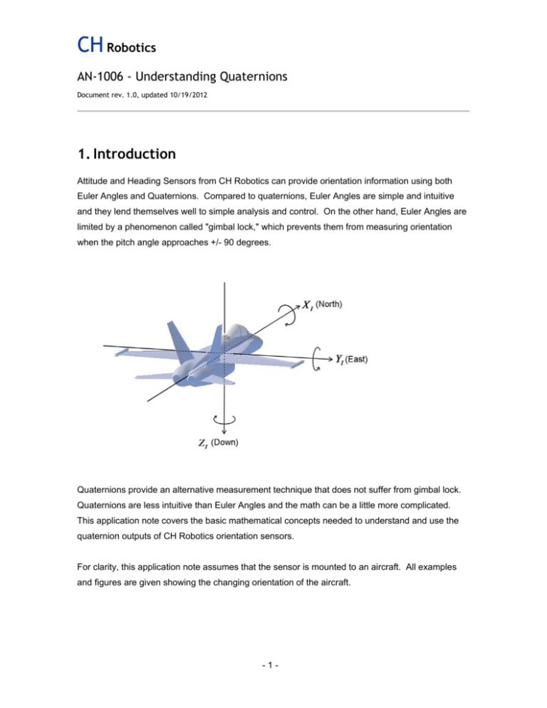
CH Robotics AN-1006 - Understanding Quaternions Document rev. 1.0, updated 10/19/2012 1. Introduction Attitude and Heading Sensors from CH Robotics can provide orientation information using both Euler Angles and Quaternions. Compared to quaternions, Euler Angles are simple and intuitive and they lend themselves well to simple analysis and control. On the other hand, Euler Angles are limited by a phenomenon called "gimbal lock," which prevents them from measuring orientation when the pitch angle approaches +/- 90 degrees. Quaternions provide an alternative measurement technique that does not suffer from gimbal lock. Quaternions are less intuitive than Euler Angles and the math can be a little more complicated. This application note covers the basic mathematical concepts needed to understand and use the quaternion outputs of CH Robotics orientation sensors. For clarity, this application note assumes that the sensor is mounted to an aircraft. All examples and figures are given showing the changing orientation of the aircraft. -1- CH Robotics AN-1006 - Understanding Quaternions Document rev. 1.0, updated 10/19/2012 Table of Contents 1. INTRODUCTION ...........................................................................................1 2. QUATERNION BASICS ................................................................................3 3. ROTATING VECTORS USING QUATERNIONS ..........................................4 DISCLAIMER..........................................................................................................7 List of Figures Figure 1 - The Inertial Frame ..............................................................................................................3 -2- CH Robotics AN-1006 - Understanding Quaternions Document rev. 1.0, updated 10/19/2012 2. Quaternion Basics A quaternion is a four-element vector that can be used to encode any rotation in a 3D coordinate system. Technically, a quaternion is composed to one real element and three complex elements, and it can be used for much more than rotations. In this application note we'll be ignoring the theoretical details about quaternions and providing only the information that is needed to use them for representing the attitude of an orientation sensor. The attitude quaternion estimated by CH Robotics orientation sensors encodes rotation from the "inertial frame" to the sensor "body frame." The inertial frame is an Earth-fixed coordinate frame defined so that the x-axis points north, the y-axis points east, and the z-axis points down as shown in Figure 1. The sensor body-frame is a coordinate frame that remains aligned with the sensor at all times. Unlike Euler Angle estimation, only the body frame and the inertial frame are needed when quaternions are used for estimation (Application note AN1005 discusses the use of Euler Angles for attitude estimation). Figure 1 - The Inertial Frame -3- CH Robotics AN-1006 - Understanding Quaternions Document rev. 1.0, updated 10/19/2012 b Let the vector q i be defined as the unit-vector quaternion encoding rotation from the inertial frame to the body frame of the sensor: q bi a b c d , T (1) where T is the vector transpose operator. The elements b, c, and d are the "vector part" of the quaternion, and can be thought of as a vector about which rotation should be performed. The element a is the "scalar part" that specifies the amount of rotation that should be performed about the vector part. Specifically, if is the angle of rotation and the vector v x vy T v z is a unit vector representing the axis of rotation, then the quaternion elements are defined as a cos(0.5 ) b v x sin(0.5 ) (2) c v y sin(0.5 ) d v z sin(0.5 ) In practice, this definition needn't be used explicitly, but it is included here because it provides an intuitive description of what the quaternion represents. CH Robotics sensors output the quaternion q bi when quaternions are used for attitude estimation. 3. Rotating Vectors Using Quaternions b The attitude quaternion q i can be used to rotate an arbitrary 3-element vector from the inertial frame to the body frame using the operation 0 v B q bi (q bi ) 1 . vI (3) That is, a vector can rotated by treating it like a quaternion with zero real-part an multiplying it by the attitude quaternion and its inverse. The inverse of a quaternion is equivalent to its conjugate, -4- CH Robotics AN-1006 - Understanding Quaternions Document rev. 1.0, updated 10/19/2012 which means that all the vector elements (the last three elements in the vector) are negated. Equation (3) also uses quaternion multiplication, which has its own definition as well. Define quaternions q1 a1 b1 c1 d1 and q 2 a 2 T b2 c2 d 2 . Then the quaternion product T q1q 2 is given by a 1a 2 - b1 b 2 - c1c 2 - d1d 2 a 1b 2 + b1a 2 + c1d 2 - d1c 2 . q1q 2 a 1 c 2 - b 1 d 2 + c1 a 2 + d 1 b 2 a d + b c - c b + d a 1 2 1 2 1 2 1 2 (4) To rotate a vector from the body frame to the inertial frame using Equation (3), two quaternion multiplies as defined in Equation (4) are required. Alternatively, the attitude quaternion can be used to construct a 3x3 rotation matrix to perform the rotation in a single operation. The rotation matrix from the inertial frame to the body frame using quaternion elements is defined as a 2 b 2 c 2 d 2 Rib (q bi ) 2bc 2ad 2bd 2ac 2bc 2ad a b c d 2cd 2ab 2 2 2 2cd 2ab . a 2 b 2 c 2 d 2 2bd 2ac 2 (5) Then the rotation from the inertial frame to the body frame can be performed using the matrix multiplication v B Rib (q bi ) v I . (6) Regardless of whether quaternion multiplication or matrix multiplication is used to perform the rotation, the rotation can be reversed by simply inverting the attitude quaternion before performing the rotation. By negating the vector part of the quaternion vector, the operation is reversed. -5- CH Robotics AN-1006 - Understanding Quaternions Document rev. 1.0, updated 10/19/2012 4. Converting Quaternions to Euler Angles CH Robotics sensors automatically convert the quaternion attitude estimate to Euler Angles even when in quaternion estimation mode. This means that the convenience of Euler Angle estimation is made available even when more robust quaternion estimation is being used. If the user doesn't want to have the sensor transmit both Euler Angle and Quaternion data (for example, to reduce communication bandwidth requirements), then the quaternion data can be converted to Euler Angles on the receiving end. The exact equations for converting from quaternions to Euler Angles depends on the order of rotations. CH Robotics sensors move from the inertial frame to the body frame using first yaw, then pitch, and finally roll. This results in the following conversion equations: 2(ab cd ) , 2 2 2 2 a b c d arcsin2(bd ac) , arctan (7) 2(ad bc) . 2 2 2 2 a b c d arctan See application note AN1005 for more details about the meaning and application of Euler Angles. When implementing equations (7), the atan2 function should be used instead of atan so that the output range is correct. Note that when converting from quaternions to Euler Angles, the gimbal lock problem still manifests itself. The difference is that since the estimator is not using Euler Angles, it will continue running without problems even though the Euler Angle output is temporarily unavailable. When the estimator runs on Euler Angles instead of quaternions, gimbal lock can cause the filter to fail entirely if special precautions aren't taken. -6- CH Robotics AN-1006 - Understanding Quaternions Document rev. 1.0, updated 10/19/2012 Disclaimer This document is provided as reference only; "typical" device specifications must be evaluated by the end-user. CH Robotics reserves the right to modify this document and the products it describes without notice. CH Robotics products are not intended for use in weapons systems, aircraft, life-saving or life-sustaining systems, automobiles, or any other application where failure could result in injury, death, property damage, or environmental damage. -7-
