Experiment #2: Single Phase Transformer - ECE
advertisement

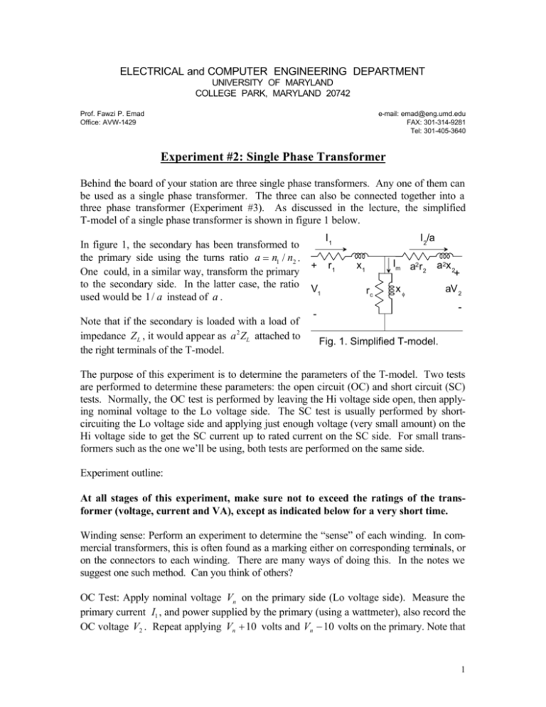
ELECTRICAL and COMPUTER ENGINEERING DEPARTMENT UNIVERSITY OF MARYLAND COLLEGE PARK, MARYLAND 20742 Prof. Fawzi P. Emad Office: AVW-1429 e-mail: emad@eng.umd.edu FAX: 301-314-9281 Tel: 301-405-3640 Experiment #2: Single Phase Transformer Behind the board of your station are three single phase transformers. Any one of them can be used as a single phase transformer. The three can also be connected together into a three phase transformer (Experiment #3). As discussed in the lecture, the simplified T-model of a single phase transformer is shown in figure 1 below. In figure 1, the secondary has been transformed to the primary side using the turns ratio a = n1 / n2 . One could, in a similar way, transform the primary to the secondary side. In the latter case, the ratio used would be 1/ a instead of a . Note that if the secondary is loaded with a load of impedance Z L , it would appear as a 2 ZL attached to the right terminals of the T-model. I1 r1 + V1 I 2/a Im a2 r 2 x1 rc a2x 2 + xf aV 2 - Fig. 1. Simplified T-model. The purpose of this experiment is to determine the parameters of the T-model. Two tests are performed to determine these parameters: the open circuit (OC) and short circuit (SC) tests. Normally, the OC test is performed by leaving the Hi voltage side open, then applying nominal voltage to the Lo voltage side. The SC test is usually performed by shortcircuiting the Lo voltage side and applying just enough voltage (very small amount) on the Hi voltage side to get the SC current up to rated current on the SC side. For small transformers such as the one we’ll be using, both tests are performed on the same side. Experiment outline: At all stages of this experiment, make sure not to exceed the ratings of the transformer (voltage, current and VA), except as indicated below for a very short time. Winding sense: Perform an experiment to determine the “sense” of each winding. In commercial transformers, this is often found as a marking either on corresponding terminals, or on the connectors to each winding. There are many ways of doing this. In the notes we suggest one such method. Can you think of others? OC Test: Apply nominal voltage Vn on the primary side (Lo voltage side). Measure the primary current I1 , and power supplied by the primary (using a wattmeter), also record the OC voltage V2 . Repeat applying Vn +10 volts and Vn −10 volts on the primary. Note that 1 in these cases I2 = 0 , thus I1 = Im . Since | r1 + jx1| = | Z1| << | rc || jxφ | , we can assume the voltage drop on Z1 is negligible, thus the voltage on the shunt is practically equal to V1 . Knowing the current I m , voltage V1 , and power P1 , the shunt components rc and xφ can be computed. Perform this computation for the three sets of readings you just completed. SC Test: Apply a short circuit with an ammeter on the secondary side. Apply a small voltage on the primary side and measure this voltage, the current it supplies and the power to the transformer. Slowly, very slowly, increase the voltage applied to the primary side till rated current is reached on the secondary side. Record the values of V1 , I1 , P1 , and I2 = ISC = In . Decrease the primary voltage so that I2 = 0.9 I n and repeat. Next, very quickly increase the primary voltage so that I2 = 11 . I n . Make sure to perform these steps quickly in order to avoid heating the transformer. Since the full load current I1 is much larger than the magnetizing current I m , the shunt components may be neglected. Thus, to a very good degree of approximation we have I1 = I2 / a . If we let xeq = x1 + a 2 x 2 and req = r1 + a 2 r2 , then knowing the values of V1 , I1 , and P1 , the values of xeq and req can be computed. Perform this computation for the three sets of reading you just took. See the figure on next page. Note that the SC test allows us to measure the “equivalent” series resistance and equivalent series impedance of the transformer, and not the corresponding primary and secondary parts. This is acceptable since the individual components are usually not needed. If one needs the primary and secondary components of the equivalent series parameters, these may be found be performing further measurements (we will not perform such measurements in this experiment). Next compute the efficiency of the transformer at various loads applied to the secondary. Do this at full load, half load and quarter load (resistive). The efficiency is computed as Pout η= . The losses are found from the equivalent T-model you developed in this Pout + losses experiment. How does the efficiency vary with load? The diagram to the right may be helpful in your setup of this experiment. W W 2 The autotransformer: If time permits, connect an autotransformer (to step down the source voltage) as explained in the lecture. Measure input and output voltages. Apply a suitable load, measure input and output power, input and output voltages and currents. What are the power rating of this connection compared to the normal one? How about the efficiency of this connection compared with the normal one? Include these conclusions in your report. I1 I2 /a r1 + Im r eq x1 V1 rc x eq xf + aV2 - Simplified approximate model. IH = I + VH - 1 + V1 + V2 - N1 I + N 2 x VX IL = I 2 - The autotransformer 3


