Capacitor Self
advertisement

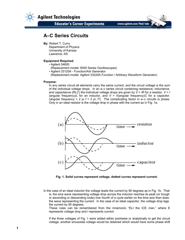
A–C Series Circuits By: Robert T. Curry Department of Physics University of Kansas Lawrence, KS Equipment Required: • Agilent 54600 (Replacement model: 6000 Series Oscilloscopes) • Agilent 33120A - Function/Arb Generator (Replacement model: Agilent 33220A Function / Arbitrary Waveform Generator) Purpose: In any series circuit all elements carry the same current, and the circuit voltage is the sum of the individual voltage drops. In an a–c series circuit containing resistance, inductance, and capacitance (RLC) the individual voltage drops are given by V = IR for a resistor, V = I (angular frequency)L for an inductor, and V = I/(angular frequency)C for a capacitor. (angular frequency = 2 pi f = 2 pi /T). The complicating factor in a–c circuits is phase. Only in an ideal resistor is the voltage drop in phase with the current as in Fig. 1a. Fig. 1. Solid curves represent voltage, dotted curves represent current. In the case of an ideal inductor the voltage leads the current by 90 degrees as in Fig. 1b. That is, the sine wave representing voltage drop across the inductor reaches its peak (or trough or ascending or descending node) one–fourth of a cycle earlier on the time axis than does the wave representing the current. In the case of an ideal capacitor, the voltage drop lags the current by 90 degrees. These rules can be remembered from the mnemonic “ELI the ICE man,” where E represents voltage drop and I represents current. If the three voltages of Fig. 1 were added either pointwise or analytically to get the circuit voltage, another sinusoidal voltage would be obtained which would have some phase shift 1 φ with respect to the current. In general, this phase shift would be neither 0 degrees nor ± 90 degrees, but would depend on the amplitudes of the three voltages. A phasor diagram is constructed by regarding the instantaneous voltage drops to be the y–components of rotating “vectors.” Fig. 2 shows a phasor diagram which would generate the voltage phases of Figure 1 if allowed to rotate counterclockwise. The circuit voltage V and its phase angle φ are found by “vector” addition of the phasors representing VR VL and VC. Procedure: R – L – C Series Circuit 1. Hook up the circuit of Fig. 3. Connect the Ch 2 input of the oscilloscope to point a to monitor the voltage across the 10 ohm resistor. This is important because it has the same phase as the current. Use a frequency generator output of 1 kHz (i.e. a period of 1 ms on the oscilloscope graticule.) 2. Connect the Ch 1 input of the oscilloscope to point b to measure the amplitude of the voltage drop across the 0.22μF capacitor. (The 10 ohm resistor voltage is negligible in comparison.) Measure also the phase of Vc with respect to I. Call this φc . 3. Interchange C and the 50 mH inductor in the circuit and repeat step 2 for VL and φL. Note: real inductors have significant series resistance of their own, so you may find φL is noticeably less than 90 degrees. 4. Interchange L and the 1K ohm resistor and measure VR and φR. 5. Connect the Ch 1 input directly to the output of the function generator and measure the circuit voltage V and phase angle φ. 2 96 E19-3 6. Construct to scale on graph paper a phasor diagram showing VL , VC , VR and their “vector” sum V. On the same diagram show the measured value of V. Do your results agree within reasonable limits? If time permits, repeat the experiment after resetting the frequency of the function generator to 2 kHz (i.e. 0.5 ms period.) Series Resonance: Of particular interest is the case where φ = 0. With the apparatus in the configuration of step 5, adjust the frequency until the circuit voltage is in phase with the current. Compare this resonant frequency with that predicted from. These experiments have been submitted by third parties and Agilent has not tested any of the experiments. You will undertake any of the experiments solely at your own risk. Agilent is providing these experiments solely as an informational facility and without review. AGILENT MAKES NO WARRANTY OF ANY KIND WITH REGARD TO ANY EXPERIMENT. AGILENT SHALL NOT BE LIABLE FOR ANY DIRECT, INDIRECT, GENERAL, INCIDENTAL, SPECIAL OR CONSEQUENTIAL DAMAGES IN CONNECTION WITH THE USE OF ANY OF THE EXPERIMENTS. 3


