Catalytic & Hydrocracking: Refining Processes Notes
3CH2236 Advanced Petroleum Refining Processes
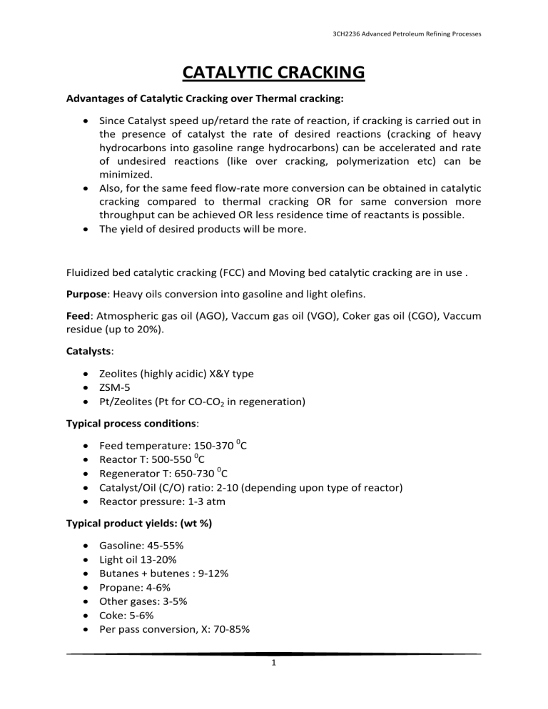
CATALYTIC CRACKING
Advantages of Catalytic Cracking over Thermal cracking:
Since Catalyst speed up/retard the rate of reaction, if cracking is carried out in the presence of catalyst the rate of desired reactions (cracking of heavy hydrocarbons into gasoline range hydrocarbons) can be accelerated and rate of undesired reactions (like over cracking, polymerization etc) can be minimized.
Also, for the same feed flow-rate more conversion can be obtained in catalytic cracking compared to thermal cracking OR for same conversion more throughput can be achieved OR less residence time of reactants is possible.
The yield of desired products will be more.
Fluidized bed catalytic cracking (FCC) and Moving bed catalytic cracking are in use .
Purpose : Heavy oils conversion into gasoline and light olefins.
Feed : Atmospheric gas oil (AGO), Vaccum gas oil (VGO), Coker gas oil (CGO), Vaccum residue (up to 20%).
Catalysts :
Zeolites (highly acidic) X&Y type
ZSM-5
Pt/Zeolites (Pt for CO-CO
2
in regeneration)
Typical process conditions :
Feed temperature: 150-370
Reactor T: 500-550 0 C
Regenerator T: 650-730
0
0
C
C
Catalyst/Oil (C/O) ratio: 2-10 (depending upon type of reactor)
Reactor pressure: 1-3 atm
Typical product yields: (wt %)
Gasoline: 45-55%
Light oil 13-20%
Butanes + butenes : 9-12%
Propane: 4-6%
Other gases: 3-5%
Coke: 5-6%
Per pass conversion, X: 70-85%
1
3CH2236 Advanced Petroleum Refining Processes
Catalytic cracking processes:
Types: Fixed Bed Catalytic Cracking, Moving Bed Catalytic Cracking & Fluidised Bed
Catalytic Cracking
1.
Fixed Bed Catalytic Cracking : obsolete due to problem in regeneration of catalyst and heat control in regeneration of fixed bed. Heat supply problem as cracking is an endothermic process.
2.
Moving Bed Catalytic Cracking: 10-20% of catalytic cracking is carried out using this process in old refineries.
Residence time of catalyst: 80-90 minutes, reactor temperature: 500 o
C, Catalyst to Oil ratio : 4-7
Thermofor Moving Bed Catalytic Cracker
2
3CH2236 Advanced Petroleum Refining Processes
Houdri moving bed Catalytic Cracker
Advantages of Houdri moving bed Cracker:
Low maintenance cost
High cost activity
Flexibility in charged stocks and conversions
Once through conversion: 60%, over all conversion using recycling: 90%
Octance no of gasoline obtained: 85-90
3
3CH2236 Advanced Petroleum Refining Processes
3.
Fluidised Bed Catalytic Cracking (FCC)
(also known as, Fluid catalytic cracking or Riser-Reactor or Flexi FCC)
Typical capacity:
H.P. Refinery: 7500 B/day.
Catalyst Circulation rate: 8 T/hr.
Catalyst hold up in cracker: 15 T
Catalyst hold up in regenerator: 19 T
Catalyst Particle size : 40-80
m
S.A. = 500m
2
/g for fresh and 200 m
2 g for spent.
Reactor temperature: 465-510
0
C
P = 1.5 atm
Advantages of FCC:
No heat transfer problem for cracking reaction. Heat is supplied by hot regenerated catalysts. Since the entire bed is in fluidization mode better control of temperature.
Regenerator is moving bed type so effective removal of coke from the spent catalysts.
Self-sustained in terms of heat requirement.
Since residence time is 5-6 seconds in riser reactor, cracking can be carried out at high temperature keeping coke formation minimal.
Per pass conversion is higher compared to fixed bed and moving bed. By providing recycling over all 90% conversation can be obtained.
Catalyst details :
Zeolite is a crystalline Alumina-silicate material.
Al and silicon atoms form tetrahedral, which are linked by shared oxidation atoms.
More than 200 zeolites are available.
As Alumina increases, Acidity increases.
High S.A. 300 to 500 m
High acidity.
Favourable for catalytic cracking
Pore size: 60-80A 0
.
2 g.
(Too low pore size causes the problem in ‘C’ removal, where as large pore size decreases cracking.)
Bronsted acid sites are responsible for the cracking.
4
3CH2236 Advanced Petroleum Refining Processes
Typical Zeolite structure
During course of reaction Bronsted acid sites are converted into Lewis sites which are converted back into bronsted sites in regenerator using steam and high temperature. The conversion is shown in above diagram.
X & Y Zeolites,
Na
P
Al
p
Si
102-p
O
384.
gH
2
O
P = 96 to 74 for X zeolite
74 to 48 for Y zeolite g = 250 to 270
ZSM-5 (Zeolite Socony Mobil – 5),
Na
n
Al
n
Si
96–n
O
192
·16H
2
O (0<n<27). Patented by Mobil Oil Company
5
3CH2236 Advanced Petroleum Refining Processes
Typical FCC
FCC Reaction variables:
1.
Temperature:
Cracker: Being cracking as an endothermic reaction high temperature is favourable but at too high temperature over cracking and other side reactions predominant so optimum temperature of riser reactor is kept from 450 to 550 o
C.
At, H.T. → olefins (C
3
,C
4
)
M.T. → gasoline
L.T. → Improper cracking
6
3CH2236 Advanced Petroleum Refining Processes
Regenerator: 600-700
0
C (Adiabatic moving bed reactor)
Regenerator reaction
C + O
2
→ CO
2
+ CO , ΔH= highly exothermic (more than 300 kJ/mol)
This heat is gained by the catalysts and temperature is raised up to 750 o
C. The heated catalyst particles from regenerator are used to exchange heat with preheated feed to convert it into vapour and for supplying heat of cracking reaction.
2.
Pressure:
1 -2 atm, As such no effects
L.P ↑ ‘C’ formation
H.P. ↓ light H.C.
3. Riser contact-time: 2 to 6 sec
When the catalysts are fresh 2 sec and over the period of time the contact-time is increased up to 6 sec.
Short contact-time and high temperature results in High O.N. compounds.
4.
Catalyst to oil (C/O) ratio: 2 to 7
Ratio has to be varied due to ↓ in catalytic activity with usage of it even if regenerating the fresh catalyst. There is a permanent loss in activity due to pore blocking, sintering and loss of active sites.
5.
Slip velocity: 𝑠𝑙𝑖𝑝 𝑣𝑒𝑙𝑜𝑐𝑖𝑡𝑦 = 𝑣𝑎𝑝𝑜𝑢𝑟 𝑣𝑒𝑙𝑜𝑐𝑖𝑡𝑦 𝑐𝑎𝑡𝑎𝑙𝑦𝑠𝑡 𝑣𝑒𝑙𝑜𝑐𝑖𝑡𝑦
=
𝑉𝑎𝑝𝑜𝑢𝑟 𝑣𝑒𝑙𝑜𝑐𝑖𝑡𝑦 𝑣𝑎𝑝𝑜𝑢𝑟 𝑣𝑒𝑙𝑜𝑐𝑖𝑡𝑦 − 𝑇𝑒𝑟𝑚𝑖𝑛𝑎𝑙 𝑣𝑒𝑙𝑜𝑐𝑖𝑡𝑦 𝑜𝑓 𝑝𝑎𝑟𝑡𝑖𝑐𝑙𝑒
As slip velocity ↑ contact between vapour and particles become poor → Improper cracking.
7
3CH2236 Advanced Petroleum Refining Processes
Heat balance: Breakdown of FCC Heat Requirements
Heat consuming event
Heat up and vaporize fresh feed
Heat for recycled oil
Heat of reaction(ΔH= +ve)
Heat: steam
Heat : losses
Heat: air to regeneration temp.
Heat: C to from Reactor Temp. to
Regeneration Temp.
40-50%
0-10%
15-30%
2-8%
2-5%
15-25%
1-2%
% of Total
1160-2325 KJ/Kg
Note:
The recent trend in refineries for FCC is to get maximum propylene gas from the FCC unit as its demand is very high and profit is significant once it is converted into polypropylene. Presently Sinopec FCC catalyst gives 15-20% propylene yield in FCC.
FCC Numerical (Class Notes)
8
3CH2236 Advanced Petroleum Refining Processes
Hydrocracking
H
2
+ Catalyst + Heat based Cracking.
Hydrotreating deals with removal of impurities using mild operating conditions, low
H
2
P.P. and different Catalysts then hydrocracking.
Hydrocracking deals with the in addition to removal of impurities, cracking of highly heavy feed stock to get the products like Gases, Diesel, Gasoline, Naphta & Fuel oil.
Purpose: Heavy H.C. to lighter H.C.
Feed: VGO, HGO, LGO, visbreaker gas oil, FCC residue, VDU residue (up to 10%).
Products: Gases, Naphtha (Gasoline), Diesel, kerosene.
Licensors: Axens (IFP) Exxon Mobil
Shell global solution UOP
Catalyst: Co-Mo or Ni-Mo or Ni-W on Zeolite
Ni-Mo or Ni-W on amorphous silica alumina.
Pd on Zeolite
Catalytic Reaction Conditions:
Reactor temperature: 315-425 0 C (over all Exothermic reaction)
Pressure: 80 to 170 atm.
Typical Reactions:
IN addition to HDS, HDN, HDO, HDM reactions which remove the impurities present following reactions occur:
Hydrocracking of paraffins R-R’ + H
2
→ RH + R’H ( Both HC are SATURATED which is desired for gasoline, diesel and jet fuel )
Isomerization n-R.H → i-R-H
Aromatic saturation
Dealkylation of Aromatic Rings.
9
3CH2236 Advanced Petroleum Refining Processes
10
3CH2236 Advanced Petroleum Refining Processes
Coke formation:
Due to H
2
presence, coke formation is slow or very less.
Without regeneration catalyst can be used for 1 yr.
High pressure of process also minimizes the coke formation.
Process flow:
Trickle Bed Reactor & Ebullated Bed Reactor
Trickle Bed Reactor: H.C.(liq.) + H
2
(gas) } reactants Pass down over a fixed bed of catalysts.
Once -Through Trickle Bed Hydrocracker
Hot water injected to remove NH
3
& H
2
S at the oulet
Series of fractionators are used to separate L.N, H.N, middle distillates.
Unconverted oil.
Feed B.P. range: 340-550
0
C , API: 22, Sp. g.r. : 0.922, S=2.5%,N:950rpm.
Product quality: Research O.N. 79-80 (Heavy Naphtha)
Jet fuel: Flash point: 38
0
C , Smoke point: 34mm, Aromatics: 7%.
Diesel: Cetane No: 55, flash point: 52
0
C.
11
3CH2236 Advanced Petroleum Refining Processes
Ebullating Bed Hydrocracker
The limitation of trickle bed reactor is that in the fixed bed the contact among hydrogen (gas), hydrocarbon oil (liquid) and catalysts (solid) is not proper. Also the heat removal is an issue. To overcome all these Ebullated bed hydrocracker has been developed that is basically a bubbling fluidised bed reactor in which high velocity of hydrogen, oil and recycle oil keep the catalyst particle in fluidised form with high density at bottom and low density at top of the reactor. The great turbulence generate due to recycling and fluidization facilitate better temperature control and proper contact among all phases
Over all conversion upto 90% & better quality of products can be achieved using Ebullated bed reactor.
Ebullated Bed Hydrocracker
12
3CH2236 Advanced Petroleum Refining Processes
Comparison of Cracking Operations
Parameters Thermal
Cracking
Temperature, o
C 450-500
Fixed bed
Catalytic Cracking
450-520
Moving bed
Catalytic
Cracking
450-520
Fluidised bed
Catalytic
Cracking
500-520
HT can be allowed due to very short contact time
Good Control Reactor
Temperature control
Regenerator
Temperature control
Pipe reactor:: easy control
NA
Product Quality Very Poor due to uncontrolled cracking
Once through conversion, %X
40-50
10-15 Contact time of feed, S
Contact time of catalyst
Regenerator
Contact time, min
NA
NA
Throughput
Coke formation control
Major problem
Major problem
Poor quality due to improper heat supply
50-60
6-10
NA
2-3 hrs lowest
Fair, reactor dia decreases medium
Very high coke due to fixed bed.
Poor Control due to coke formation
TOO HIGH High External heat requirement
Gasoline yield
C/O ratio NA
Poor Poor
NA
Moderate problem
Good Control Good Control
Good quality Very quality
50-60
6-10
60-80 min
6-10 min
60-70
2-6
2-6 sec
10-12 min good medium High
Good control Good control due to FCC &
Regenerator
Moderate are in closed loop
Heat
Sufficient
Self
Good
4-7
Very Good
2-7
13
3CH2236 Advanced Petroleum Refining Processes
Coking
Product known as PET-COKE most widely used in electrode manufacturing and fuel.
Indian Pet-Coke is having best quality due to less sulphur presents in Indian crude oil.
Methods:
1.
Hot Oven: The asphalt or tars or pitches heated in oven at 1000-1200 o
C in absence of air for 18 hrs to get the coke. OBSOLATE due to high temperature process.
2.
Thermal cracking or Dubb’s two Coil method: Two step process – thermal cracking in coil reactor followed by further cracking in evaporators where liquid oil is also removed. Operating temperature 600-700 o
C.
Feed: VDU residue, high mol wt feed.
3.
Delayed Coking: Most widely used.
Feed same as thermal cracking and tar, pitch etc.
Steps: Furnace heating where cracking starts and then mass is transferred to large DRUMS (4-5 m dia & 14-20 m Ht) where rest of the cracking is carried out in 16-18 hrs. Drums are arranged in series/parallel so that continuous feed treatment is applied.
Typical yield is 30% for heavy oil & 80% for tar and pitch as feed.
4.
Fluid Coking: latest refineries install this type of fluidised bed coker.
Bubbling fluidisation in unique way is used in this method. COKE particles themselves act as a catalyst. The coke formation grows on smaller particles in reactor (just like crystal growth by nucleation in crystallization). In regenerator some fraction of large coke particles are burned partially so that dia of them reduce and are sent back to the reactor which act as a catalyst. The heat generated is used to supply the heat of reaction in reactor.
5.
Flexi-Coking
6.
Contact Coking
14
3CH2236 Advanced Petroleum Refining Processes
Alternative Fuels ( conventional & non-conventional)
1 ). Natural Gas (Methane)
Compressed Natural Gas (CNG) : used for automobiles
Pressurised Natural Gas (PNG) : used for household cooking
Liquefied Natural Gas (LNG) : one of the mode of NG transportation
Synthetic Natural Gas (SNG) : NG production from biomass or coal
Shale Gas : NG obtained from Shale Rocks.
Steps for obtaining SNG:
Coal or Biomass gasification to produce CO and H
2
mixture known as producer gas. Gas cleaning.
Water-Gas-shift reaction to increase CO:H2 ratio to 3.
Methanation reaction for Methane production followed by conditioning of
SNG.
Shale Gas Production: About 100 trillion m
3
natural gas is trapped inside the shale porous rocks. The major problem is the extraction of methane from the porous structure of shale stone available at very much depth in earth crust. Since the methane is trapped in pores of stones extraction requires lots of drilling and vacuum type of methods. Unlike conventional extraction of NG or crude oil from earth crust, for shale gas multiple vertical and horizontal holes are made to extract the gas. The cost is very high, however in Canada and USA the commercial production has been started.
Gas to Liquid Fuels (GTL)
The efforts are also being put to produce liquid fuels from the Natural gas. Steps are
Synthesis Gas production followed by Fischer-Tropsch (F-T) synthesis to produce liquid fuels. The research is going on to produce liquid fuels in SINGLE step by catalytic reactions.
LPG:
mixture of propane and butane liquefied and stored at 15 atm.
Propane: 25, Butane: 75% (i &n-butane)
Used for domestic heating but can also be used for automobiles.
LPG= Dual cars.
2). Coal
15
3CH2236 Advanced Petroleum Refining Processes
Technologies for generation of Fuels from Coal must be developed in order to meet the significant rise in the demand of fuels. Coal as it is used as a fuel however SNG or
Liquefied fuels are under research/pilot scale which can be used in the automobiles.
Conversion of Coal into liquid fuel process is known as the coal to Liquid (CTL).
It’s a two step process in which synthesis gas is produced from the coal followed by generation of liquid fuel vii Fischer-Tropsch (F-T) synthesis. SASOL is the world leader company in this area.
3). Biomass
Since biomass is having C and H the fuels can also be produced from them. The latest trend is to produce liquid fuels knows as Biomass-to-liquid (BTL) and SNG. The same two step process is used for production of liquid fuels from biomass. Some of the processes are as follows:
Ethanol reforming to produce hydrogen
Ethanol production, Bio-methanol under research.
Bio-diesel
Hydrogen
Under Second Generation Bio-Fuels the aim is to produce fuels from any kind of
Biomass Waste/residue whether it is food waste or agriculture residues.
4.) Hydrogen
Hydrogen is considered as the future energy carrier or Fuel.
Since it is a clean fuel from environment point of view lots of pressure is there to develop the technologies for hydrogen production. Many fossil and renewable fuels are being tested for the low cost hydrogen production. The major source of hydrogen is sea water. By water splitting hydrogen can be produced for that electrosplitting method is there but cost is very high. In future nuclear fission based water splitting will be the viable option. Hydrogen offers many advantages as far as conventional automobiles are concerned. It offers almost zero emission and very high well to wheel efficiency.
5.) Shale Oil: 30 millon barrel of shale oil is available in the shale stones.
6.) Alcohols :
Good burning quality but low calorific values .
All above uses “SI” engine.
Alcohols can be blended in the conventional fuels.
7.) Bio-diesel:
90-98% Triglycerides with small amount of mono & di-glycerides, free fatty acids etc.
16
3CH2236 Advanced Petroleum Refining Processes
Veg. Oils from castor, zethropa, corn, cotton seed, linseed, peanut, soyabean, palm, sunflower.
High viscosity compared to diesel fuel due to large molecular structure and mass (30-40 centi-stoke)
Mol. wt. 3 times the diesel.
Vol. heating value 39-40 mJ/Kg, Diesel 45 mJ/Kg
Problems in engine:
High viscosity leads problem of injection (poor automization), insufficient mixing, high flash point→ low volatility, more carbon deposits, high gum formation.
‘Trans-esterification’ is done to ↓
.
Tri glyceride + 3 CH
3
OH → Glycerol + Fatty acid methyl esters
(known as BIODIESEL)
Characteristics are close to Diesel
C.N. =45 to 64
Viscosity↓ by a factor of 8 to 10 compared to Triglyceride.
8.) Petro crops:
Several plants with their latex contain petroleum like H.C. which can be extracted using organic solvents known as ‘Bio crude’.
These plants known as the ‘Petro crops’ plants found in uncultivated areas cactus plants.
9.) Plastic & Rubber waste to Fuel: The waste non-recyclable plastic and rubbers can be converted into diesel fractions using appropriate technology and catalysts.
OTHERS FROM PHOTOCOPIES PROVIDED
17
