Airspeed
David F. Rogers
email: dfr@usna.navy.mil
http://www.nar-associates.com
One of the most important instruments on your panel is the airspeed indicator, or ASI. Do you
know how it works? When was the last time you had it calibrated? Have you ever had it calibrated?
For given flight conditions, do you get POH book values? If you don’t get book values, then your
ASI may be incorrect. Alternatively, your manifold pressure gauge, tachometer, and/or fuel flow
gauge may be incorrect. All these must be accurate to insure that you get book values. However,
let’s talk about how the ASI works. In a second article we’ll talk about how you can calibrate the
ASI using a GPS receiver.
The airspeed indicator is a differential pressure instrument that depends on the pitot-static
system. Remember the discussion of the pitot-static system from ground school. You do remember
that, don’t you? I didn’t think so. If I didn’t teach it, I probably wouldn’t remember it either. The
design of the airspeed indicator is based on Bernoulli’s equation. There I go again expecting you to
remember something from ground school. What’s Bernoulli’s equation? Well, Bernoulli’s equation
says that the total energy in an airflow is the sum of the potential energy due to air pressure and
the kinetic energy due to motion of the air, or
Total energy = Potential energy + Kinetic energy
Translated into aircraft terms, we have
Total or Pitot pressure = Static pressure + Dynamic pressure
Let me write this as an equation
PTotal = PStatic + 1/2ρV 2
(1)
where PTotal is the total or pitot pressure, PStatic is the static or local atmospheric pressure and
1/2ρV 2 is the dynamic pressure, with ρ the local density and V the velocity (TAS).
Now how do we get velocity out of this equation? Well, let’s solve the equation for the velocity
V =
2(PTotal − PStatic )
ρ
(2)
This result says that if we can measure the total (or pitot) pressure along with the static (or local
atmospheric) pressure and know the local density, we can find the velocity of the aircraft. How do
we do this?
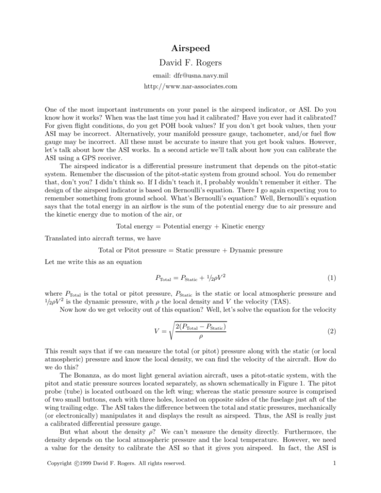
The Bonanza, as do most light general aviation aircraft, uses a pitot-static system, with the
pitot and static pressure sources located separately, as shown schematically in Figure 1. The pitot
probe (tube) is located outboard on the left wing; whereas the static pressure source is comprised
of two small buttons, each with three holes, located on opposite sides of the fuselage just aft of the
wing trailing edge. The ASI takes the difference between the total and static pressures, mechanically
(or electronically) manipulates it and displays the result as airspeed. Thus, the ASI is really just
a calibrated differential pressure gauge.
But what about the density ρ? We can’t measure the density directly. Furthermore, the
density depends on the local atmospheric pressure and the local temperature. However, we need
a value for the density to calibrate the ASI so that it gives you airspeed. In fact, the ASI is
c
Copyright 1999
David F. Rogers. All rights reserved.
1
Total Pressure
Port, P
Pitot Probe
Static Pressure Port, PStatic
Airspeed
Indicator
Figure 1.
Schematic of a separate pitot-static source system.
calibrated using the density at sea level on a standard day, i.e. ρSSL = 0.002378 slugs/cubic foot.
Consequently, the ASI seldom, if ever, reads the actual velocity (TAS) of the aircraft. As a result,
Equation(2) reduces to
(3)
V = Constant PTotal − PStatic
How do you find TAS? What does the ASI read? Figure 2 illustrates the process of correcting
the number read off the ASI, called Indicated AirSpeed (IAS), to give TAS. First, no instrument
reads precisely the correct value even with precisely the correct input. The difference between the
actual value and the indicated value is called instrument error. In essence this is a mechanical
problem. The POH assumes zero instrument error. Consequently, in Figure 2 instrument error is
lumped together with position error.
Position error results from incorrect pressure values read by the pitot probe and the static
ports. Except at very high angles of attack, the pitot probe is quite accurate. However, the static
pressure port can be very inaccurate. What we want the static pressure port to measure is the
atmospheric pressure well ahead of the aircraft, i.e., in what is called by aeronautical engineers
the free stream. Obviously, we cannot do this directly without sticking a long probe out ahead of
the airplane. Except on flight test aircraft, that is neither a good nor a practical idea. Instead,
aeronautical engineers look for a position on the aircraft that gives the same static pressure reading
as that in the free stream. This is not easy to do. No matter where you locate the static pressure
port(s), the static pressure reading depends on the aircraft configuration and flight attitude, e.g.,
clean, gear down, flaps down, gear and flaps down, high angle of attack, slipping or skidding. For
late model Bonanzas, the POH shows that in the clean configuration the position error is about
Figure 2.
Corrections to IAS that yield TAS.
c
Copyright 1999
David F. Rogers. All rights reserved.
2
1%. However, with flaps extended the error jumps to about 3.5%. In each case the calibrated
airspeed (CAS) is lower than the indicated airspeed (IAS). To give some idea of the importance of
the static pressure port, at 100 mph it takes an error in the static pressure reading of only 0.0036
pounds per square inch to yield an error of one mph in the IAS! Incidentally, Part 23 of the FARs
requires that the error, including position error, in the ASI be less than 3%, or 5 knots throughout
the normal operating range.
If the airspeed is a significant fraction of the speed of sound, then compressibility effects
induce an error in the pressure seen by the pitot probe. Unless you are lucky enough to fly a
turbine Bonanza in the flight levels, compressibility effects are negligible. Consequently, given the
Bonanza’s small position error in the clean configuration, and assuming zero instrument error, it
is generally safe to assume that indicated airspeed is equal to equivalent airspeed (EAS) in cruise
flight. This brings us to the all important density altitude correction to get true airspeed from the
equivalent airspeed.
Using Equation (2) with the actual density, ρ, gives us true airspeed (TAS), whereas using
Equation (2) with the value for standard sea level density gives equivalent airspeed (EAS). Dividing
Equation (2) for TAS by Equation (2) for EAS gives
2(PTotal − PStatic )
ρ
T AS
VTAS
=
=
=
VEAS EAS
2(PTotal − PStatic )
ρSSL
ρSSL
=
ρ
1
σ
where σ = ρ/ρSSL is the ratio of the actual density to that at sea level on a standard day. Alternatively, we write this equation as
T AS = EAS
EAS
ρSSL
= √
ρ
σ
(4)
This equation says that the TAS depends on the density, i.e., the altitude; but we already knew
that, so what was the point. How do we find the actual density? I’m glad you asked. We find it
indirectly. There is a relation between the pressure, the temperature and the density, called the
perfect gas equation. It is
P =ρRT
(5)
where here R is the so called universal gas constant and T is the absolute temperature which we
get by adding 460 to the temperature in degrees Fahrenheit. Now, if we rearrange this equation
we can find the density, provided we know the pressure and temperature. Here we go,
ρ=
P
RT
(6)
Here, P the pressure is obtained by setting 29.92 in the Kohlsman window of the altimeter and
looking the value up in a table of pressure versus altitude in the standard atmosphere (see Table
1). The absolute temperature, T , is obtained by reading the OAT gauge and adding 460 to the
reading. Once we have the actual density we can find σ and hence the TAS from the EAS.
Alternatively, we substitute Equation (6) into Equation (4) and rewrite the TAS in terms of
the EAS, the pressure and the temperature
TAS = 2 EAS
t + 460
P
(7)
where t is the temperature in degrees Fahrenheit and P is the pressure in pounds per square foot
at a given pressure altitude (see Table 1). The E-6B solves Equation (6) when used to determine
the true airspeed from the equivalent airspeed.
c
Copyright 1999
David F. Rogers. All rights reserved.
3
Table 1
Altitude
Pressure
feet
psf
0
2116.2
500
2078.3
1,000
2040.9
2,000
1967.7
3,000
1896.7
4,000
1827.7
5,000
1760.9
6,000
1696.0
7,000
1633.1
8,000
1572.1
9,000
1512.9
10,000
1455.6
11,000
1400.0
12,000
1346.2
Now that we have all these equations, let’s use
them to explain a classic ASI phenomenon. We have
all read the advice that if the pitot tube is blocked the
ASI behaves like an altimeter. That’s always seemed
like the hard way to explain it. Let’s use Equation
(3) to explain what happens in this case.
If the pitot tube is blocked, then the pitot pressure, PTotal, does not change. Looking at Equation
(3) if the static pressure, PStatic , changes, then the indicated airspeed changes. So, if the altitude increases
the static pressure decreases, the difference between
the total and static pressure increases and the airspeed increases. Conversely, if the altitude decreases
the static pressure increases, the difference between
the total and static pressure decreases and the airspeed decreases. As a practical matter, if the airspeed
and the altimeter are both increasing or decreasing,
then you may have a blocked pitot tube, e.g., from ice
in the clouds. If this happens, use the attitude indicator to level the aircraft, confirm that the aircraft is in
level flight using the altimeter and rate-of-climb indicator and turn on the pitot heat to clear the blockage.
c
Copyright 1999
David F. Rogers. All rights reserved.
4

