Nesscap Ultracapacitor
Datasheet - 2.7V / 2000F Cell
FEATURES
»
»
»
»
»
High performance product with low RC time constant
Long lifetimes with over 1,000,000 duty cycles
Rated capacitance of 2000F
Threaded terminals for easy integration
Compliant with RoHS and REACH requirements
SPECIFICATIONS
* Image is not to scale
Electrical
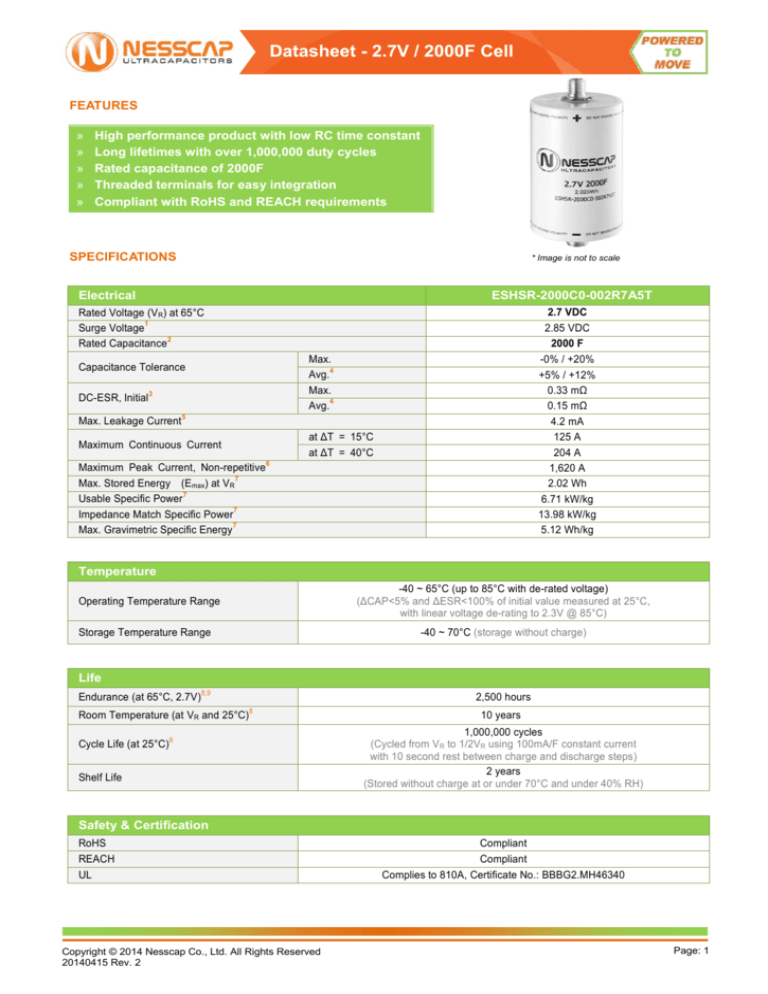
ESHSR-2000C0-002R7A5T
2.7 VDC
2.85 VDC
2000 F
-0% / +20%
+5% / +12%
0.33 mΩ
0.15 mΩ
4.2 mA
125 A
204 A
1,620 A
2.02 Wh
6.71 kW/kg
13.98 kW/kg
5.12 Wh/kg
Rated Voltage (VR) at 65°C
1
Surge Voltage
2
Rated Capacitance
Max.
4
Avg.
Max.
4
Avg.
Capacitance Tolerance
DC-ESR, Initial
3
Max. Leakage Current
5
at ΔT = 15°C
at ΔT = 40°C
Maximum Continuous Current
Maximum Peak Current, Non-repetitive
7
Max. Stored Energy (Emax) at VR
7
Usable Specific Power
7
Impedance Match Specific Power
7
Max. Gravimetric Specific Energy
6
Temperature
-40 ~ 65°C (up to 85°C with de-rated voltage)
(ΔCAP<5% and ΔESR<100% of initial value measured at 25°C,
with linear voltage de-rating to 2.3V @ 85°C)
Operating Temperature Range
Storage Temperature Range
-40 ~ 70°C (storage without charge)
Life
Endurance (at 65°C, 2.7V)
8,9
Room Temperature (at VR and 25°C)
Cycle Life (at 25°C)
2,500 hours
8
8
Shelf Life
10 years
1,000,000 cycles
(Cycled from VR to 1/2VR using 100mA/F constant current
with 10 second rest between charge and discharge steps)
2 years
(Stored without charge at or under 70°C and under 40% RH)
Safety & Certification
RoHS
Compliant
REACH
Compliant
UL
Copyright © 2014 Nesscap Co., Ltd. All Rights Reserved
20140415 Rev. 2
Complies to 810A, Certificate No.: BBBG2.MH46340
Page: 1
Nesscap Ultracapacitor
Datasheet - 2.7V / 2000F Cell
THERMAL
Characteristics
ESHSR-2000C0-002R7A5T
Typical Thermal Resistance, Rth (Housing)
2.9 °C/W
Typical Thermal Capacitance, C th
520 J/°C
Cont. Current to ΔT = 15°C
125 A
Cont. Current to ΔT = 40°C
204 A
PHYSICAL
Drawing
See Note on Mounting
Dimensions
D (±0.2)
L (±0.3)
H (±0.125)
Nominal Weight
10
ESHSR-2000C0-002R7A5T
60.2 mm
103.0 mm
13.0 mm
395 g
Shock & Vibration
Shock Specification
Vibration Specification
Copyright © 2014 Nesscap Co., Ltd. All Rights Reserved
20140415 Rev. 2
SAE J2464
ISO 16750 (Table 14)
Page: 2
Nesscap Ultracapacitor
Datasheet - 2.7V / 2000F Cell
NOTE
1. Surge Voltage
˃ Absolute maximum voltage, not repeated and for no longer
than 1 second.
2. Rated Capacitance
˃ Constant current charge with 10mA/F to VR
˃ Constant voltage charge at VR for 5min
˃ Constant current discharge with 10mA/F to 0.1V
6. Max. Current
˃ Current for 1sec discharging from rated voltage to half
rated voltage under constant current discharging mode.
(A) =
Where
is the discharge time (sec) and
is the capacitance (F);
is the ESRDC (Ω);
is the rated voltage (V).
is 1 sec in this case;
˃ Max. Current should not be used in normal operation and is only
provided as a reference value.
7. Energy & Power
˃ Max. Stored Energy at VR =
=
Where
Where
is the measurement starting voltage, 0.8ⅹVR (V);
is the measurement end voltage, 0.4ⅹVR (V);
is the time from discharge start to reach
(s);
is the time from discharge start to reach
(s);
is the absolute value of the discharging current (A).
is the capacitance (F);
is the rated voltage (V).
˃ Usable Specific Power, IEC 62391-2 (W/kg) =
˃ Impedance Match Specific Power (W/kg) =
3. ESR (Equivalent Series Resistance)
˃ ESRDC
- Constant current charge to VR
- Constant voltage charge at VR for 5min
- Constant current discharge to 0.1V
˃ Gravimetric Specific Energy (Wh/kg) =
8. Lifetime
˃ End-of-Life Conditions
- Capacitance:
-30% from rated min. value
- ESR:
+100% from max. ESR value
9. Endurance
˃ Conditions
- Temperature:
65 ± 2°C
- Test duration :
2500 (+48/-0) h
- Applied voltage: VR ± 0.02V
- Capacitance and ESR measurement are made at 25°C
Where
10. Mounting
is the ESRDC (Ω);
is the voltage drop for 10ms (V);
is the discharge current (A).
4. Average (or Typical)
˃ Percentage spread that may be present in one shipment
5. Leakage Current
˃ The capacitor is charged to the rated voltage at 25°C.
˃ Leakage current is the current at 72 hours that is required to
keep the capacitor charged at the rated voltage
˃ Mounting should be designed in such a way as to not place undue
mechanical stress on the terminals
˃ Do not exceed the max torque value of 8Nm when assembling threaded
type cells.
˃ Provide adequate spacing in between cells to ensure required insulation
strength for the application.
˃ Provide clearance above the safety vent and do not position anything
above the safety vent that may be damaged by vent rupture.
˃ Welding recommendation for weldable cells available on
www.nesscap.com under Support > Download.
The contents of this document are subject to change without notice. Values presented are thought to be accurate at the time of writing. Nesscap does not
guarantee that the values are error-free, nor does Nesscap make any other representation, warranty or guarantee that the information is accurate, correct,
reliable or current. For more information, you can reach us at one of following contacts
Nesscap Energy Inc.
Nesscap Energy Inc.
Nesscap Co., Ltd.
Nesscap China
Suite 3800, Royal Bank Plaza,
South Tower, 200 Bay Street,
P.O. Box 84, Toronto,
Ontario, M5J 2Z4
S24040 Camino Del Avion
#A118, Monarch Beach,
California, 92629
17, Dongtangiheung-ro 681beon-gil,
Giheung-gu, Yongin-si, Gyeonggi-do
Room 1608, Block N, Cangson
Building, Chegonmiao,
Futian District, Shenzhen City,
P.R.C
Nesscap Energy
10A, prospect 60-letiya
Oktyabrya Moscow, 117036
CANADA
USA
REPUBLIC OF KOREA
CHINA
RUSSIA
Nesscap Energy GmbH
EASTERN EUROPE
marketing@nesscap.com
Copyright © 2014 Nesscap Co., Ltd. All Rights Reserved
20140415 Rev. 2
Beerengarten 4
D-86938 Schondorf
GERMANY
info@nesscap-energy.de
Page: 3


