Solids - MhChem.org
advertisement
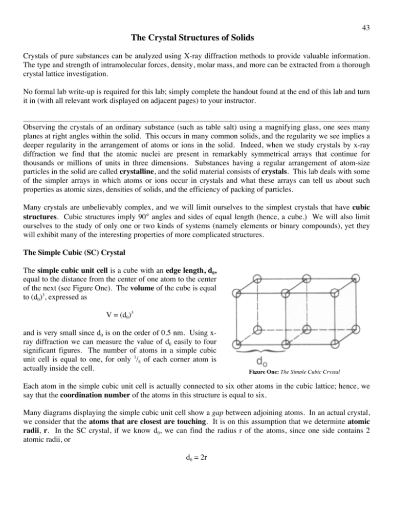
43 The Crystal Structures of Solids Crystals of pure substances can be analyzed using X-ray diffraction methods to provide valuable information. The type and strength of intramolecular forces, density, molar mass, and more can be extracted from a thorough crystal lattice investigation. No formal lab write-up is required for this lab; simply complete the handout found at the end of this lab and turn it in (with all relevant work displayed on adjacent pages) to your instructor. Observing the crystals of an ordinary substance (such as table salt) using a magnifying glass, one sees many planes at right angles within the solid. This occurs in many common solids, and the regularity we see implies a deeper regularity in the arrangement of atoms or ions in the solid. Indeed, when we study crystals by x-ray diffraction we find that the atomic nuclei are present in remarkably symmetrical arrays that continue for thousands or millions of units in three dimensions. Substances having a regular arrangement of atom-size particles in the solid are called crystalline, and the solid material consists of crystals. This lab deals with some of the simpler arrays in which atoms or ions occur in crystals and what these arrays can tell us about such properties as atomic sizes, densities of solids, and the efficiency of packing of particles. Many crystals are unbelievably complex, and we will limit ourselves to the simplest crystals that have cubic structures. Cubic structures imply 90° angles and sides of equal length (hence, a cube.) We will also limit ourselves to the study of only one or two kinds of systems (namely elements or binary compounds), yet they will exhibit many of the interesting properties of more complicated structures. The Simple Cubic (SC) Crystal The simple cubic unit cell is a cube with an edge length, d0, equal to the distance from the center of one atom to the center of the next (see Figure One). The volume of the cube is equal to (d0)3, expressed as V = (d0)3 and is very small since d0 is on the order of 0.5 nm. Using xray diffraction we can measure the value of d0 easily to four significant figures. The number of atoms in a simple cubic unit cell is equal to one, for only 1/8 of each corner atom is actually inside the cell. Figure One: The Simple Cubic Crystal Each atom in the simple cubic unit cell is actually connected to six other atoms in the cubic lattice; hence, we say that the coordination number of the atoms in this structure is equal to six. Many diagrams displaying the simple cubic unit cell show a gap between adjoining atoms. In an actual crystal, we consider that the atoms that are closest are touching. It is on this assumption that we determine atomic radii, r. In the SC crystal, if we know d0, we can find the radius r of the atoms, since one side contains 2 atomic radii, or d0 = 2r 44 for simple cubic crystals. Knowing the radius, we can calculate d0, and then we can calculate the volume of the unit cell. Knowing that one atom occupies the simple cubic cell, we can calculate the mass of the unit cell (using the molar mass and Avogadro’s number), and from this we can determine the density using the volume of the cell. Essentially no elements crystallize in the simple cubic structure, however, due to the inefficiency of the packing. The atoms in the simple cubic crystal are farther apart then they need to be, and inspection of the SC lattice will reveal a large hole in the center of the unit cell. Only about 52% of the cell volume is occupied by atoms, and more “empty space” means less stabilization for the crystal structure. The Body Centered Cubic (BCC) Crystal In a body centered cubic crystal, the unit cell still contains the corner atoms present in the SC structure, but the center of the cell now contains an additional atom. This means that every BCC crystal structure holds two net atoms (eight atoms are 1/8 within the cell, and one whole atom within the center of the cell for two net atoms). The edge length, d0, can be determined using simple geometry from the cube diagonal (see Figure Two). The cube diagonal reaches across the cube, from an atom in the lower left front to an atom in the upper right back, or from any other appropriate combination. Geometry dictates the following relationship between the cube body diagonal and the edge length, d0: cube diagonal = 3 d0 The cube diagonal encompasses 4 radii lengths, and d0 can be expressed in terms of the radius of the atom: d0 = Figure Two: Body Centered Cubic Crystal 4r 3 The quantity d0 can be used to find the volume of the cube; hence, this relationship is important for BCC cubic systems. In a BCC lattice, each atom touches eight other atoms, and the coordination number is eight. The BCC lattice is much more stable than the SC structure, in part due to the higher coordination number. Many metals at room temperature display the BCC lattice, including sodium, chromium, tungsten and iron. Note that there are two atoms per unit cell in the BCC crystal. BCC crystals are more efficient than SC crystals, occupying approximately 68% of the total available volume. 45 Close Packed Structures Although many elements prefer the BCC crystal arrangement, still more prefer structures in which the atoms are close packed. In close packed structures there are layers of atoms in which each atom is in contact with six others, as in the sketch below: This is the way in which billiard balls lie in a rack or the honeycomb cells are arranged in a bees' nest. It is the most efficient way one can pack spheres, with about 74% of the volume in a close packed structure filled with atoms. There is more than one way whereby close packed crystal structures can be stacked. One of the stacking methods is cubic and is called the Face Centered Cubic (FCC). The other is called hexagonal packing. We shall look at both close packed structures. The Face Centered Cubic (FCC) Crystal In the face centered cubic crystal unit cell there are atoms in each corner of the cell (as in the SC cell discussed earlier) and there is another atom at the center of each of the six faces. This means that FCC cubic systems consist of four net atoms per unit cell (eight atoms are 1/8 within the cell, and six faces hold an atom which is 1/2 within the cell for four net atoms). See Figure Three. The edge length d0 can be determined in an FCC crystal from the face diagonal which is defined as the distance across one face of the cube. Using geometry, we can find the edge length from the face diagonal using the following equation: face diagonal = 2 d0 The face diagonal encompasses 4 radii lengths, and d0 can be expressed in terms of the radius r: d0 = Figure Three: Face Centered Cubic Crystal 4r 2 This expression can be used to find the volume of the cube; hence, this relationship is important for FCC cubic systems. The coordination number in an FCC lattice is 12, implying that FCC lattices are quite stable. 46 It is worthwhile to look at the types of holes within the FCC lattice for they will be helpful when discussing ionic solids later. One type of hole is in the center of the FCC lattice; this type of hole is called an octahedral hole (Figure Four) because the six atoms around it define an octahedron. There are twelve octahedral holes in an FCC lattice. In an ionic crystal, the anions often occupy the sites of the atoms in your cell, and there is a cation in the center of the octahedral hole. The ratio of the maximum radius of the cation, r+, compared with the maximum radius of the anion, r-, is often calculated to determine what type of hole to use for the cations. If the ratio r+/r- is greater than 0.414 but less than 0.732, the cations will be placed in octahedral holes. Figure Four: Octahedral Holes There is another type of hole in the FCC lattice called tetrahedral holes. There are eight tetrahedral holes in the FCC lattice, and each atom in a tetrahedral hole is surrounded by four complimentary atoms (hence the tetrahedron reference). If the ratio r+/r- is between 0.225 and 0.414, the cations will go into tetrahedral holes. The close-packed layers of atoms in the FCC lattice are not parallel to the unit cell faces, but rather are perpendicular to the cell diagonal. If you look down the cell diagonal, you see six atoms in a close-packed triangle in the layer immediately behind the corner atom, and another layer of close-packed atoms below that, followed by another corner atom. The layers are indeed closely packed, and as one goes down the diagonal of this and succeeding cells, the layers repeat their positions in the order ABCABC…. This implies that atoms in every fourth layer lie below one another (see Figure Five (b)). Hexagonal Packing There is another way to stack the layers as in the FCC lattice, above. The first and second layers will always be in the same relative positions, but the third layer could be below the first one if it were shifted properly. This results in a close-packed structure in which the order of the layers is ABABAB… (see Figure Five (a)) The crystal obtained from this arrangement of layers is not cubic but hexagonal. It is another common structure for metals. Cadmium, zinc and manganese Figure Five: Hexagonal Close Packing (left) and Cubic Close Packing (right) 47 have this structure. As you might expect, the stability of this structure is very similar to that of FCC crystals. We find that simply changing the temperature often converts a metal from one form to another. Calcium, for example, is FCC at room temperature, but if heated to 450 °C it converts to close-packed hexagonal. Crystal Structures of Some Common Binary Compounds We have now dealt with all of the possible cubic crystal structures for metals. It turns out that the structures of binary ionic compounds (i.e. MX where M is the cation and X is the anion in 1:1 stoichiometry) are often related to these metal structures in a relatively simple way. In many ionic crystals, the anions (which are large compared to cations – recall the periodic properties of elements and ions) are essentially in contact with each other in either an SC or FCC structure. The cations go into the cubic, octahedral or tetrahedral holes depending on the cation-anion radius ratios r+/r-. The idea to remember is that cations tend to go in holes in which it will not quite fit. This increases the unit cell size from the value it would have if the anions were touching, which reduces the Coulombic repulsion energy. According to the radius-ratio rule, large cations go into cubic holes, smaller cations go into octahedral holes, and the smallest cations go into tetrahedral holes. One can calculate the radius ratio and then determine the location of the cations: If: r+/r- > 0.732 0.732 > r+/r- > 0.414 0.414 > r+/r- > 0.225 cations go into cubic holes cations go into octahedral holes cations go into tetrahedral holes These are the three common cubic structures of binary compounds. The radius-ratio rule allows us to predict the structure a given compound will have. It does not always work, but it is correct more often than not. Examples follow for each of the common binary compounds. The NaCl Crystal (Octahedral Cation Holes) To apply the radius rule to NaCl, we need to calculate the r+/rratio. From tables we find r+ for Na+ equals 0.0950 nm and rfor Cl- equals 0.181 nm. The radius ratio is 0.095/0.181 = 0.525, and the ratio implies that the Na+ ions will be placed in octahedral holes since this value is less than 0.732 and greater than 0.414 (See Figure Six.) To build a NaCl lattice, we place a Cl- ion in each FCC position. Figure Six: The NaCl crystal The Na+ ions go into each of the octahedral holes in the FCC lattice. There are twelve octahedral holes in the FCC lattice (one on each edge), and each Na+ ion will be 1/4 in the unit cell. In addition, one sodium atom fits in the center of the FCC lattice of Cl- atoms. Therefore, the number of Na+ ions per NaCl unit cell will be (12 octahedral atoms * 1/4) + (1 Na+ in center) = 4 net Na+ atoms per unit cell. We have already seen that a FCC lattice holds four net atoms, which means each NaCl unit cell contains four net Cl- ions. Since there are four net Na+ cations and four net Cl- anions, the resulting structure is Na4Cl4 or, as is more commonly expressed in empirical form, NaCl. The edge of an octahedral ionic solid can be related to the cation and anion radii using d0 = 2r+ + 2r- 48 The CsCl Crystal (Cubic Cation Holes) Cesium chloride is a binary ionic compound just like NaCl, but due to the larger r+ value of the Cs+ ion (0.169 nm), the r+/r- radius ratio is 0.933. Using the radius-ratio rule, we find that the Cs+ cations should be placed in cubic holes (see Figure Seven). The structure of CsCl will look like the BCC lattice except that the atom in the center will be Cs+ while the corner atoms will be Clions. Note that this structure is not BCC because the corner and center atoms have different identities. The resulting empirical formula for cesium chloride is (1 net Cs+ atom in center) + (8 Cl- atoms * 1/8 each atom in unit cell) = CsCl. Figure Seven: The CsCl Crystal The edge of a cubic ionic solid can be related to the cation and anion radii using d0 = 2r+ + 2r3 The ZnS Crystal (Tetrahedral Cation Holes) € To determine the structure of ZnS (another binary compound), we first determine the r+/rradius ratio. From tables we find r+ for Zn2+ is 0.0740 nm while r- for S2- is 0.184 nm. The r+/r- radius ratio is, therefore, 0.402, and this implies that the Zn2+ cations will be placed in tetrahedral holes. (See Figure Eight) To build the ZnS crystal, first construct a FCC crystal lattice using S2- ions. The Zn2+ cations occupy four of a possible eight tetrahedral holes. The resulting formula for ZnS will consist of four Zn atoms (each tetrahedral cation is completely within the unit cell) and four S atoms (a FCC lattice has four net atoms), and the resulting empirical formula is ZnS (zinc(II) sulfide). Figure Eight: The ZnS Crystal 49 Summary of Crystal Lattice Types Figure Nine shows the three main cubic unit crystal types that we have explored. Recall that binary ionic compounds utilize these shapes – in their own way – by placing the cations in the octahedral, tetrahedral, or cubic "holes" within the lattice; the anions occupy the "normal" cubic positions. The r+/r- radius ratio determines which of the three possible holes in which the cations are placed. Relevant relationships between the edge length, d0, and the cation and anion radii are given in Figure Ten. Lattice Type # net atoms per cell d0 (edge) in relation to r Simple Cubic 1 d0 = 2r Body Centered Cubic 2 d0 = Face Centered Cubic 4 4r 3 d0 = 4r 2 Figure Nine: Summary of the Three Cubic Unit Cell Types Binary Cell Type # net molecules per cell radius ratio qualifying values d0 (edge) in relation to r Cubic 1 r+/r- > 0.732 d0 = 2r+ + 2r3 Octahedral 4 0.732 > r+/r- > 0.414 d0 = 2r+ + 2r- d0 = Figure Ten: Summary of the Three Common Binary Cell Types € Tetrahedral 4 0.414 > r+/r- > 0.225 € 2r+ + 2r2 50 The Crystal Structures of Solids Complete the following problems using the table of radii at the bottom of this page. All answers must be provided on the worksheet, and relevant work must be stapled to the back of the worksheet. 1. Experimentally determine the density of an unknown metal solid to at least three significant figures using any equipment found in your lab drawer. Explain the process (and show calculations) used to determine the density in three sentences or less on both this sheet and in your lab notebook. 2. What element forms a face centered cubic cell, has a density of 8.92 g/cm3, and a radius of 128 pm? 3. Chromium forms a body centered cubic crystal. If the length of an edge is 2.884 angstroms, calculate the density (g/cm3) and the radius of a chromium atom in angstroms. 4. Sodium forms a body centered cubic crystal. Calculate the density of sodium metal. Propose a simple experiment to confirm your calculated density of sodium in the lab. (Note: use the table of radii below!) 5. Calculate the radius ratio for TlBr. What kind of cation holes will be filled in a crystal of TlBr? 6. Calculate the radius ratio for KI. What kind of cation holes will be filled in a crystal of KI? 7. Consider a cubic array of bromide ions in which the anions are touching along the face of the cube. What is the maximum radius (in angstroms) that a cation could have and still fit in the octahedral holes on the edges of the FCC unit cell? 8. Clausthalite is a mineral composed of lead(II) selenide. The mineral adopts a NaCl octahedral-type structure. If the density of PbSe is 8.27 g/cm3, calculate the radius of the lead(II) ion. (The radius of selenide ion is given below.) 9. NaBr forms a crystal lattice similar to octahedral NaCl. Calculate the density of NaBr. Propose a simple experiment to confirm your calculated density in the lab. Atom Na Se Cs Cl Br Zn Tl K S I conversion V = edge3 Atomic Radius (pm) 186 117 265 99.0 114 135 170. 227 104 133 density Ionic Radius (pm) 95.0 191 (Se2-) 169 181 196 74.0 147 (Tl+) 133 184 220. molar mass (g/mol) Avogadro (6.022 x 10²³) radius ↔ edge ↔ volume ↔ mass (g) ↔ moles ↔ atoms / molecules 1 pm = 10-12 m / 1 Å = 10-10 m / 1 cm = 10-2 m 4 atoms = 1 fcc cell, etc. 51 Worksheet: The Crystal Structures of Solids Name: All final answers to the questions (which appear on the previous page) must be provided on this worksheet, and relevant work must be stapled to the back on separate paper to receive full credit. 1. Density of unknown metal (g cm-3): ________ Unknown letter: ________ Brief description (with calculations) of method used to calculate density: 2. Element: ______ 3. Density of Cr (g cm-3): _________ Radius of Cr (angstroms): ________ 4. Density of sodium (g cm-3) = ________ Proposed Experiment: 5. Radius ratio for TlBr = _________ Type of cation holes = _________ 6. Radius ratio for KI = _________ Type of cation holes = _________ 7. Maximum radius of cation (angstroms): ________ 8. Radius of the lead(II) ion (angstroms): ________ 9. Density of NaBr (g cm-3): ________ Proposed Experiment: 52
