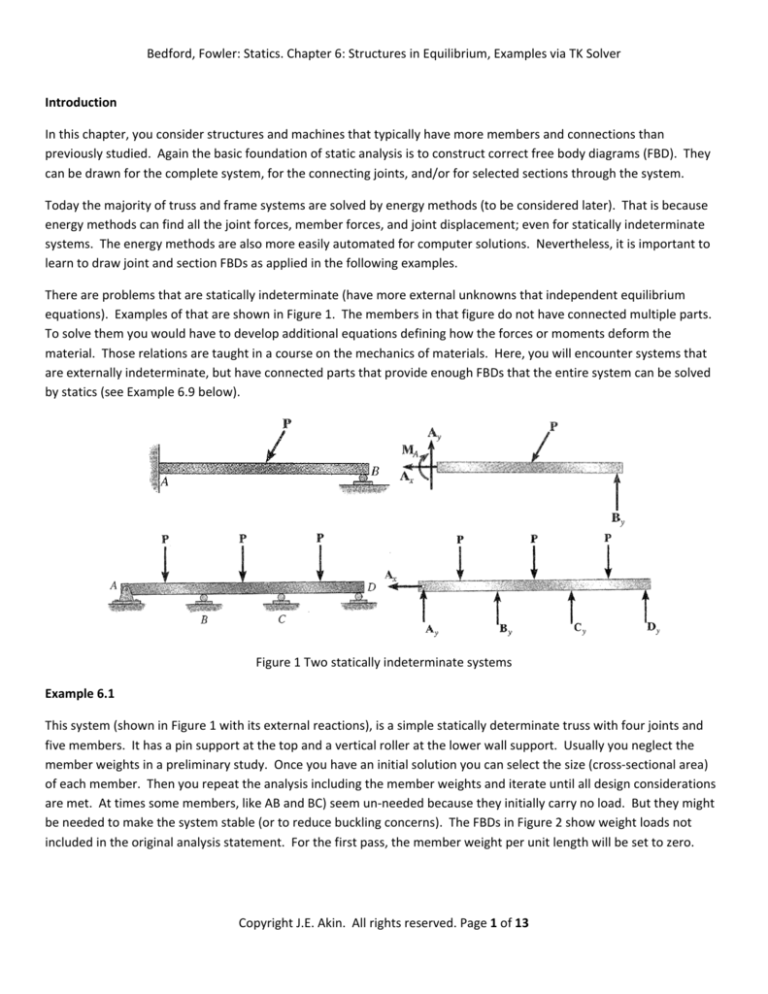
Bedford, Fowler: Statics. Chapter 6: Structures in Equilibrium, Examples via TK Solver Introduction In this chapter, you consider structures and machines that typically have more members and connections than previously studied. Again the basic foundation of static analysis is to construct correct free body diagrams (FBD). They can be drawn for the complete system, for the connecting joints, and/or for selected sections through the system. Today the majority of truss and frame systems are solved by energy methods (to be considered later). That is because energy methods can find all the joint forces, member forces, and joint displacement; even for statically indeterminate systems. The energy methods are also more easily automated for computer solutions. Nevertheless, it is important to learn to draw joint and section FBDs as applied in the following examples. There are problems that are statically indeterminate (have more external unknowns that independent equilibrium equations). Examples of that are shown in Figure 1. The members in that figure do not have connected multiple parts. To solve them you would have to develop additional equations defining how the forces or moments deform the material. Those relations are taught in a course on the mechanics of materials. Here, you will encounter systems that are externally indeterminate, but have connected parts that provide enough FBDs that the entire system can be solved by statics (see Example 6.9 below). Figure 1 Two statically indeterminate systems Example 6.1 This system (shown in Figure 1 with its external reactions), is a simple statically determinate truss with four joints and five members. It has a pin support at the top and a vertical roller at the lower wall support. Usually you neglect the member weights in a preliminary study. Once you have an initial solution you can select the size (cross‐sectional area) of each member. Then you repeat the analysis including the member weights and iterate until all design considerations are met. At times some members, like AB and BC) seem un‐needed because they initially carry no load. But they might be needed to make the system stable (or to reduce buckling concerns). The FBDs in Figure 2 show weight loads not included in the original analysis statement. For the first pass, the member weight per unit length will be set to zero. Copyright J.E. Akin. All rights reserved. Page 1 of 13 Bedford, Fowler: Statics. Chapter 6: Structures in Equilibrium, Examples via TK Solver Figure 1 A five member planar truss Figure 2 Truss joint free body diagrams (including weight) However, they are included in the supplemented equilibrium rules given in Figure 3. That example assumes equal areas. Often members are made the same size to ease their assembly. Of course, you could modify the rules to give each member a different cross‐section and supply the material weight per unit volume. The initial results, neglecting weight, are given in Figure 4. They agree with the text values. Then assuming a reasonable weight per unit length of 100 N/m the reactions and member forces change significantly as seen in Figure 5. Including the member weights always causes members AB and BC to help in supporting the weight. Note that when weights are included the tension in AC is greater than that in member CD. There is also about a 40% increase in the compression of member T_BD. There are more restrictions in selecting members to restrict compression than there is for tension members. For truss members, half the weight acts on each end. For most members you only know that the weight acts at the center of mass, or centroid (reviewed in the next chapter). Here, the center of gravity is simply the mid‐point of the member. You could rewrite the sum of moments about point A using lever arms measured from those points. You will get the same results as above (try it). Once you have found the reactions needed to hold the system in equilibrium (or from material in the next chapter), you can determine the horizontal distance to the point through which the weight of all the members acts. In the rules provided, that point is denoted as CG_x. Copyright J.E. Akin. All rights reserved. Page 2 of 13 Bedford, Fowler: Statics. Chapter 6: Structures in Equilibrium, Examples via TK Solver Example 6.2 This is a small input modification of the above example. None of the rules has to be changed. Here, the goal is to find the downward force at D that would either cause a maximum compression of 2 kN, or 10 kN in tension (note the difference in allowable loadings). To solve this, first neglect the weight and, set compression member T_BC to have a force of ‐2,000 N and solve for the applied force. Then set the maximum tension (in AC) to 10,000 N and solve for the same force. Those two results are given in Figure 6. Figure 3 Geometry and equilibrium rules (including member weights) Copyright J.E. Akin. All rights reserved. Page 3 of 13 Bedford, Fowler: Statics. Chapter 6: Structures in Equilibrium, Examples via TK Solver Figure 4 Truss force results, neglecting member weights Figure 5 Force results including truss member weights Copyright J.E. Akin. All rights reserved. Page 4 of 13 Bedford, Fowler: Statics. Chapter 6: Structures in Equilibrium, Examples via TK Solver Figure 6 Finding compression and tension limits for applied force Dy For the compression limit, the downward force at point D cannot exceed 1,200 N. The tension limit restricts the applied load at D to about 5,140 N downward. Clearly, the compression limit governs the allowable load here. Who would the force limits change if you include the member weights? (Try it and see.) Example 6.7 This cable‐frame‐pulley system, and its external FBD, is shown in Figure 7. The pulley is frictionless, so the cable tension just changes in direction, not in value. Pin joints are employed, and the weight supported by the cable is 40 lb. Initially the member weights will be ignored. There are three external unknowns (Ax, Ay, Dx) so they could be found just from the FBD of the system. The five internal unknowns (Cx, Cy, Gx, Gy, R) will require a minimum of five equations, involving at least two general two‐dimensional FBDs. The cable tension is equal to the weight by inspection (for a statics problem, but not so later in dynamics). From the pulley FBD you see there is only one unknown in each direction to oppose the cable forces. So, you should also see by inspection that Gx = T and Gy = T. The geometry rules and selected equilibrium rules are given in Figure 9. It is important to note that the FDB has the assumed direction (tension or compression) given on each FBD. Those assumptions are used in the rules given in the Rules Sheet. If a force is computed to have a negative sign, then that means the force is actually in the opposite direction. Some authors always recommending that Copyright J.E. Akin. All rights reserved. Page 5 of 13 Bedford, Fowler: Statics. Chapter 6: Structures in Equilibrium, Examples via TK Solver an unknown force is in tension. Then a sign change simply means the force is compressive, and you do not have to refer back to your FBD to know the true state of a force. Figure 7 Cable‐frame‐pulley system Figure 8 Available free body diagrams Copyright J.E. Akin. All rights reserved. Page 6 of 13 Bedford, Fowler: Statics. Chapter 6: Structures in Equilibrium, Examples via TK Solver Figure 9 Selected force and moment equilibrium for the cable‐frame‐pulley system Again, remember that you have a wide choice in where you select points in a FBD about which you require moment equilibrium. You can select as many moment equilibrium points as you wish in any FBD. Therefore, the choices given in Figure 9 are not unique. The external equilibrium rules are sufficient to find the support forces. However, to determine the internal connection forces TK requires a starting guess for one of the unknowns. This is seen in Figure 10, where the diagonal member BE is guessed to be in tension. The converged iterative solution of the equilibrium equations is given in Figure 11. Those results show that the diagonal member is actually in compression. Note that the diagonal brace BE carries the largest force in the system. Where would you place connection point E in order to reduce the diagonal brace force? Try changing the rule for the tangent of the angle to check your reasoning. Copyright J.E. Akin. All rights reserved. Page 7 of 13 Bedford, Fowler: Statics. Chapter 6: Structures in Equilibrium, Examples via TK Solver Figure 10 External equilibrium results and initial guess for internal results Figure 11 Internal equilibrium results Example 6.7, with member weights As the next step in the study of the above system, you would include the weights of the members and the pulley. The weight of the cable is neglected since it is taken to be straight. (Including the weight of a cable requires solving a differential equation for a non‐straight shape, as will be seen in a later chapter.) Member BE is a truss member (two‐
force member), so its weight is split between it two support ends (on members AD and CG). The vertical and horizontal bars have more than two support points. Their weights are taken to act at their center points (which is always true for rectangular shaped members). The horizontal force equilibrium equations are unchanged. Of course, the moment equilibrium equations must include the lever arm to each weight term in the FBD. The modified rules are given in Figure 12, and the new results are in Figure 13. Copyright J.E. Akin. All rights reserved. Page 8 of 13 Bedford, Fowler: Statics. Chapter 6: Structures in Equilibrium, Examples via TK Solver Figure 12 Including member weights in the cable‐frame‐pulley system Copyright J.E. Akin. All rights reserved. Page 9 of 13 Bedford, Fowler: Statics. Chapter 6: Structures in Equilibrium, Examples via TK Solver Figure 13 Forces considering the effects of member weights Copyright J.E. Akin. All rights reserved. Page 10 of 13 Bedford, Fowler: Statics. Chapter 6: Structures in Equilibrium, Examples via TK Solver Example 6.9 This is an example of a system that is statically indeterminate, but contains parts that provide additional FBds that allow a full statics solution. The truck‐trailer system has a parking brake applied only to wheel B. That is, only that wheel can apply a force tangent to the inclined plane. You also know that the internal connect between the cab and trailer at point D is a smooth pin (a ball joint in 3‐D). The planar system FBD in Figure 14 has four unknowns. However, you can only create three independent equilibrium equations. Therefore, the external forces cannot be determined from that FBD alone. You can split the two bodies apart and introduce equal and opposite forces at point D. The assumed component directions for the force at D are shown on the trailer FBD in Figure 15. Be alert for the change in directions (signs) of those components when the cab FBD is considered. In the rules given in Figure 16, the components of the weights are defined in the positive x‐ and y‐directions (but given the correct negative signs). Figure 14 Externally indeterminate truck‐trailer system Figure 15 Statically determinate trailer system and truck system You can select FBDs in any order. Start with the trailer FBD since it has only three unknowns compared to the five for the cab (and four for the system). Once you know the values of A, Dx and Dy, both the remaining FBDs will have only three unknowns each. Of course, with TK Solver you do not have to see that you can just write the rules for each FBD. Copyright J.E. Akin. All rights reserved. Page 11 of 13 Bedford, Fowler: Statics. Chapter 6: Structures in Equilibrium, Examples via TK Solver Here, rules were written for all three FBDs to provide both a solution and a validation of that solution. The outputs, in Figure 16, agree with those of the text. Figure 16 Externally indeterminate truck and trailer with determinate parts Copyright J.E. Akin. All rights reserved. Page 12 of 13 Bedford, Fowler: Statics. Chapter 6: Structures in Equilibrium, Examples via TK Solver Figure 16 Outputs for the trailer‐truck system Copyright J.E. Akin. All rights reserved. Page 13 of 13

