EXPERIENCES OF HIGH STRAIN DYNAMICS PILE TESTING
advertisement
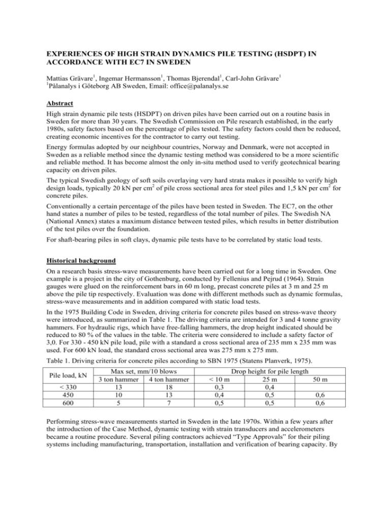
EXPERIENCES OF HIGH STRAIN DYNAMICS PILE TESTING (HSDPT) IN ACCORDANCE WITH EC7 IN SWEDEN Mattias Grävare1, Ingemar Hermansson1, Thomas Bjerendal1, Carl-John Grävare1 Pålanalys i Göteborg AB Sweden, Email: office@palanalys.se 1 Abstract High strain dynamic pile tests (HSDPT) on driven piles have been carried out on a routine basis in Sweden for more than 30 years. The Swedish Commission on Pile research established, in the early 1980s, safety factors based on the percentage of piles tested. The safety factors could then be reduced, creating economic incentives for the contractor to carry out testing. Energy formulas adopted by our neighbour countries, Norway and Denmark, were not accepted in Sweden as a reliable method since the dynamic testing method was considered to be a more scientific and reliable method. It has become almost the only in-situ method used to verify geotechnical bearing capacity on driven piles. The typical Swedish geology of soft soils overlaying very hard strata makes it possible to verify high design loads, typically 20 kN per cm2 of pile cross sectional area for steel piles and 1,5 kN per cm2 for concrete piles. Conventionally a certain percentage of the piles have been tested in Sweden. The EC7, on the other hand states a number of piles to be tested, regardless of the total number of piles. The Swedish NA (National Annex) states a maximum distance between tested piles, which results in better distribution of the test piles over the foundation. For shaft-bearing piles in soft clays, dynamic pile tests have to be correlated by static load tests. Historical background On a research basis stress-wave measurements have been carried out for a long time in Sweden. One example is a project in the city of Gothenburg, conducted by Fellenius and Pejrud (1964). Strain gauges were glued on the reinforcement bars in 60 m long, precast concrete piles at 3 m and 25 m above the pile tip respectively. Evaluation was done with different methods such as dynamic formulas, stress-wave measurements and in addition compared with static load tests. In the 1975 Building Code in Sweden, driving criteria for concrete piles based on stress-wave theory were introduced, as summarized in Table 1. The driving criteria are intended for 3 and 4 tonne gravity hammers. For hydraulic rigs, which have free-falling hammers, the drop height indicated should be reduced to 80 % of the values in the table. The criteria were considered to include a safety factor of 3,0. For 330 - 450 kN pile load, pile with a standard a cross sectional area of 235 mm x 235 mm was used. For 600 kN load, the standard cross sectional area was 275 mm x 275 mm. Table 1. Driving criteria for concrete piles according to SBN 1975 (Statens Planverk, 1975). Pile load, kN < 330 450 600 Max set, mm/10 blows 3 ton hammer 4 ton hammer 13 18 10 13 5 7 Drop height for pile length < 10 m 25 m 50 m 0,3 0,4 0,4 0,5 0,6 0,5 0,5 0,6 Performing stress-wave measurements started in Sweden in the late 1970s. Within a few years after the introduction of the Case Method, dynamic testing with strain transducers and accelerometers became a routine procedure. Several piling contractors achieved “Type Approvals” for their piling systems including manufacturing, transportation, installation and verification of bearing capacity. By testing 25 % of the piles on a project the pile load could be increased from 600 kN to 800 kN for a concrete pile with a cross sectional area of 275 mm x 275 mm. In 1984, a type approval (Typgodkännandebevis 5079/84, 1984) introduced two levels of testing percentage. If 5 % of the total number of piles were driven and tested as “test piles”, initially a total safety factor of 2,5 was required. From the results of the test piles, driving criteria were established for the project. Then, if dynamic tests were performed on 25 % of the production piles, the safety factor could be reduced to 2,0. For the test piles, following measures should be taken: Blow count (number of blows per meter of penetration) Stress-wave measurements during driving and at the end of driving Restrike after minimum 12 hours with dynamic testing in order to study setup effects or relaxation Similar rules were established for steel piles. However, the extent of testing was in fact also related to the structural strength of the piles. For steel pipe piles with diameter 100 mm to 150 mm a pile load equal to 0,35 times the structural strength was accepted if 10 % of the piles were tested dynamically. If 25 % of the piles were tested the pile load could be increased to 45 % of the structural strength. Over the years the National Road, Rail Road and Building Authorities as well as the Swedish Commission on Pile Research have developed approaches to verify the geotechnical bearing capacity from dynamic piles tests. Moreover, the procedure of installing test piles for establishing driving criteria followed by tests of the production piles has changed over the years becoming more or less only restrike test of production piles. Wave Equation Analysis (WEAP) was used in the early 1980s in order to study and explain the behaviour of the conventional gravity hammers. For example, the WEAP results showed that a small change in the stiffness of the pile cushion would have a large influence on the force in the pile, which explained the observed difference in drivability from pile to pile. The use of WEAP increased over the years. In 1994, WEAP was used to establish driving criteria in the Swedish Road Administration Code (BRO 94). The number of tested piles in Table 3 refers to a control object with a maximum length of 30 m (normally an abutment). Table 2. Design load in kN for piles driven to a penetration resistance of 10 mm/10 blows according to BRO 94. Hammer Drop height (m) 3 ton 0,3 0,4 0,5 0,3 0,4 0,5 4 ton Design load (kN) 235mm 235 mm 270 mm 270 mm 435 500 520 600 595 670 490 585 585 685 655 770 Table 3. Safety factors for piles driven to a hard soil layer and rock respectively according to BRO 94. Number of tested piles (pcs) 3 4 6 10 20 All piles Soil 1,95 1,85 1,80 1,70 1,65 1,60 Rock 1,70 1,60 1,55 1,50 1,45 1,40 Similar safety factors as in BRO 94 were used for steel piles in Rapport 98 (Bengtsson, Å. et al. 1998). In addition to verification of geotechnical capacity, the report describes design of slender steel piles with respect to structural strength of the pile. Three levels of design load were defined: 2A: Max design load 0,3 times the structural strength. The piles are driven to refusal without any testing 2B: Max design load 0,4 times the structural strength. 10 % of the piles should be tested dynamically 2C: Max design load 0,5 times the structural strength. 25 % of the piles should be tested dynamically The structural strength was defined as the yield strength times the cross sectional area of the pile. For projects other than roads and bridges, concrete piles have been tested and evaluated according to Pålgrundläggning (Olsson, C., Holm, G., 1993), a manual for piling published by the Swedish Geotechnical Institute. The test results were processed statistically as follows: The characteristic capacity Rk = (1 - k5 x v) x Rm, where k5 = coefficient according to Section 9.37:1 in Pålgrundläggning: Rm = = v = / Rm = Capacity mean value (kN) Standard deviation (kN) coefficient of variation (%) Table 4. Values of k5 in relation to number of tested piles (pcs) Number of tested piles 3 4 5 6 k5 3,15 2,68 2,46 2,33 8 10 15 20 2,18 2,1 1,99 1,93 Two load levels were defined: If 5 % of the piles were tested, the calculated characteristic capacity (Rk) should exceed 1,76 times the design load of the piles. If 25 % of the piles were tested, the calculated characteristic capacity (Rk) should exceed 1,43 times the design load of the piles. Dynamic load test in accordance with EC7 Verification of geotechnical bearing capacity by dynamic stress-wave measurements is regulated in SS-EN 1997-1:2005 Geotechnical Design. Two of the major governing bodies of the construction industry: Boverket (The Swedish National Board of Housing, Building and Planning) and Trafikverket (Swedish Transport Administration) have published two separate NAs to this standard. The two NAs are BFS 2013:10 EKS9 (Boverket, 2013) and VVFS 2004:43 (Trafikverket, 2004) together with amendments in TRVFS 2011:12 (Trafikverket, 2011). Verification of bearing capacity Rc;d by dynamic stress-wave measurements is done in DA2 (Design Approach 2) in accordance with following formula: ; ; Where t is the resistant partial factor as in Table 5. Table 5. Resistant partial factors for driven piles in DA2. For bored and CFA piles the partial factor is 0,1 higher. Resistance Symbol Trafikverket Boverket Toe 1,2 1,3 Shaft (compression) 1,2 1,3 Total/combined (compression) 1,2 1,3 1,3 1,4 Shaft (tension) ; Rc;k is the characteristic bearing capacity derived from the following formula: ; Rm : Measured values : Correlation coefficient applied to the average of Rm (as per Table 6). : Correlation coefficient applied to the minimum of Rm (as per Table 6). Rd: Model factor ; Table 6. Correlation coefficients to be applied to mean and min values of measured bearing capacity from dynamic stress-wave measurements. ξ for n = ξ5 ξ6 3 1,6 1,5 4 1,55 1,45 ≥5 1,5 1,35 ≥ 10 1,45 1,3 ≥ 15 1,42 1,25 ≥ 20 1,4 1,25 ≥ 40 All piles 1,35 1,3 1,25 1,25 The factors in Table 6 are based on bearing capacity results from dynamic high strain testing using the CASE-method. The factors can then be multiplied by the model factor (Rd) of 0,85 if the final set of the test blow is <=2 mm or if a signal matching analysis (CAPWAP) is done to confirm the result. Other rules that apply are: - if only 3 piles are tested, the size of the control object (a defined area of the foundation) should not be greater than 25 m in diameter. - piles of different types should be analyzed separately - if the superstructure is considered to transfer loads from weak to strong piles the factors can be divided by 1,1 (not applicable for Boverket) - signal matching shall be carried out for shaft bearing piles. - if geotechnical tension capacity is to be evaluated from the dynamic test results by signal matching, the model factor shall be Rd = 1,3 and only 70% of the shaft resistance can be used. - pile bearing formulas correlated to penetration and temporary compression do not apply to the above table. In addition to the above, Trafikverket has technical specifications and advices that specify in detail what test and evaluation methods to use for various pile types and soil conditions. The model factors to apply for various conditions are according to Table 7. Table 7. Model factors for shaft bearing piles in granular soils Design-/testing method Static load test Dynamic load test results evaluated by CASE-method only Dynamic load test results with signal matching Pile driving formulas with or without measurements of elastic compression Drivability simulation (i.e. WEAP analysis) Model factor, γRd comp tension 1,0 1,0 1,2 Not allowed 0,85 1,3 Not allowed Not allowed Not allowed Not allowed Table 8. Model factors for shaft bearing piles in cohesive soils Design-/testing method Static load test Dynamic load test results evaluated by CASE-method only Dynamic load test results with signal matching. Calibrated against SLT in accordance with chapter 7.5.3(1) in SS-EN 1997-1(3) Pile driving formulas with or without measurements of elastic compression Drivability simulation (i.e. WEAP analysis) Model factor, γRd comp tension 1,0 1,0 Not allowed Not allowed 1,0 1,3 Not allowed Not allowed Not allowed Not allowed Table 9. Model factors for end bearing piles Design-/testing method Model factor, γRd comp tension 1,0 Not allowed 1,0 Not allowed Static load test Dynamic load test results evaluated by CASE-method only Dynamic load test results evaluated by CASE-method only. Endbearing piles driven to rock/glacial till and test-blow penetration of S ≤ 2mm/blow. 0,85 Dynamic load test results with signal matching. 0,85 Pile driving formulas with or without measurements of elastic compression Not allowed Drivability simulation (i.e. WEAP analysis) 1,3 Not allowed Not allowed Not allowed Not allowed Driving simulation (WEAP) According to the NA of Trafikverket for driving simulation (WEAP) an additional form factor (γRd,e) 1,4 resulting in a total of 1,4 has to be applied. Putting number in the equation 1,2 1,3 1,4 2,18. factor of safety of Comparison of the two NAs and historical codes Typical geological conditions in Sweden are often soft layers (clay) overlaying dense glacial till overlaying bedrock (typically granite). The most common type of pile in Sweden is the precast concrete pile of sizes between 235-300 mm, spliced to appropriate lengths and driven with relative light hammers (4-6 tons) to relatively high blow count. Before Eurocode, typically 10% of the piles where tested, less for big projects and more for smaller jobs or where the pile loads were high. In order to compare the Swedish NAs in relation to historical codes, with regards to total factor of safety, two different examples will act as reference: a) Out of 100 production piles, 10 piles were tested. All piles were driven to high blow count (10 mm/10 blows). The penetration for the test blows were equal or less than 2 mm/ blow. b) Same as above but the piles were driven to lower blow count and the set for the test blows exceeded 2 mm/ blow. Table 10. Safety factors comparisons. Code Average Minimum End bearing Shaft bearing End bearing Shaft bearing TRVFS 2011:12 (EC7 Swe NA, Road/Railroad) 1,48 1,48 1,33 1,33 BFS 2013:10 EKS9 (EC7 Swe NA, Housing) 1,60 1,60 1,44 1,44 Bro 2004 (Road/Railroad)* 1,37 1,55 1,16 1,31 Pålgrundläggning (Concrete piles, Housing)* 1,87 1,87 Rapport 98 (Steel piles, Housing)* 1,5 1,68 1,27 1,43 *) The total safety factors for the historical codes (shaded cells) are balanced due to the fact that a partial factor (class of safety), previously applied to the resistance, is now applied to the load (10%). Comparison of total safety factors Comparing the historical codes of Bro 2004 (Trafikverket, 2004) and Rapport 98, indicate that Bro 2004 has a lower safety factor. This is in theory true, however given that the Bro 2004 states that every pier/abutment shall be considered as an individual control object, 10 % of the population is often closer to 3 piles thus the Bro 2004 and Rapport 98 have almost the same level of safety. The codes also have the same approach for piles driven as end bearing piles leading to a reduction of the safety factor by 0,2 for piles driven to refusal. Comparing the historical code of Bro 2004 with TRVFS 2011:12 the total safety factor is in reality not as big as in the table above. Given that the correlations factors can be lowered, when the superstructure is stiff enough to transfer the load from weak to strong piles (which is normally the case), the safety factors are almost the same The safety factors stated in Table 10 above for Boverket are in general terms true, but since the total safety factor is related to actual number of piles tested, the percentage of piles tested and the standard deviation of the test results can of course be higher and lower. However, in practice, Boverket has had higher safety factors than the other codes. Today, both concrete and steel piles are governed by Boverket, which in turn has lead to higher loads on concrete piles. Another result of the transition to EC7 is that the required minimum value has to be closer to the average value than before. This has in practice resulted in that the minimum measured value often set the characteristic value of the geotechnical bearing capacity. Number of piles to test The previous code for housings (Pålgrundläggning), stated the number of piles to test in percentage (5 to 25 %) of the total amount of piles. The code for road and railroad (Bro 2004) specified the numbers of actual piles but, since that number was related to a limited area (30 m x 30 m), the number of piles tested was in proportion to the actual number of piles. In contrast, the EC7 allows for as few as 4 piles to be tested as long as the geotechnical conditions are the same. Since there is generally more difficult to know if the geotechnical conditions, especially for bigger projects, are the same and the fact that testing more piles leads to a better chance to detect defect piles, it has become praxis to test a minimum of 3 piles in an area of 25 m x 25 m. This criterion is basically there for the purpose of estimating the numbers of piles to test. On the other hand, the correlations factors are assigned related to a greater numbers of piles tested, often for the whole project. One advantage of EC7 is that it specifies that test piles shall be spread out equally over the total piling area. This has not been the case in the past, except for Bro 2004. In previous codes, the factor of safety became lower in proportion to the percentage of piles tested. Pålgrundläggning had the most dramatic variation in factors of safety depending on the percentage (as well as number of piles). But also Bro 2004 and Rapport 98 allowed for lower factor of safety with increased testing. Now, this is arguably the same in EC7 but given the praxis that correlations coefficients are based on the total number of tests piles, you quickly come to the point where more piles tested are not resulting in lower factors of safety. Other geotechnical issues such as pile integrity, boulders or obstructions in the ground, highly sloping rock surface etc., can be an incentive to test more piles. Since EC7 states that each pile type should be evaluated individually, the choice of correlation factor for projects comprising many pile types is becoming difficult. It is not unusual that a project comprises piles of various dimensions, different hammers and, sometimes, varying geotechnical conditions. If the EC7 is read verbatim, this could result in excessive amount piles tested. Therefore each project must be reviewed individually. However, a practice has been developed that base the correlation coefficient on the group of piles of same material, similar dimensions and driven to refusal with the same hammer. Although, calculation of bearing capacity is always related to pile type and size. Comparison with neighbouring countries Norway Norway has a history of putting confidence in driving formulas and allows for doing only measurements of the final penetration per blow or together with quasi-elastic deformation measurements. According to Peleveiledningen (2012), the model factors to be applied to Table 6 are then 1,2 for final set measurements only or 1,1 if also quasi-elastic deformation measurements are made. For piles driven to bedrock, a prescriptive measure of the Norwegian NA is that minimum capacity to be verified is that the design load times an equivalent material coefficient of 1,25. The differences in correlation factors between Norway and Sweden practices are related to the amount of piles tested. Norway allows for only 2 piles to be tested and does not have any specifications for 40 or all piles tested. The resistance partial factor is also smaller than that used in Sweden: 1,1 (driven piles in compression), 1,2 (CFA) and 1,3 (bored piles). Denmark Denmark has a different approach to the correlation factor. The factors and are not applicable (EN 1997-1 DK NA:2010-09). Instead, using different correlation factors are applied to a pile that is dynamically tested (1,25) and a pile where the dynamic result will be extrapolated to representative piles (1,4). Denmark does also highlight that the dynamic load test has to be proved to be in good correlation with static load test. For piles driven into friction material, the characteristic capacity can be calculated numerically by using the Danish Pile Driving Formula (Den Danske Rammeformel). Finland Finland uses the same model factors as in Norway with regard to dynamic formulas. The correlation factors (Finnish NA to SFS-EN 1997-1:2004 EC7) are exactly the same as in Norway, however, they are supplemented with a percentage of the number of piles to be tested related to the total number of piles at a project, which can be useful in smaller projects (50 % equals n=10 and 100 % equals n=20). The resistance partial factor for shafts in tension are in Finland specified individually for short-term and long-term loading. Conclusions The transition to EC7 can be summarized as follows: - In theory, almost the same factors of safety for bridge foundations. - Percentage of piles tested is not included in EC7. - Concrete piles are treated the same as steel piles as far as factors of safety. Historically concrete piles have warranted higher safety factors in Swedish practise. - In past codes, an increase of piles tested generally decreased the safety factors. On the other hand, in practice, the EC7, an increase of testing does not affect the total safety factor. - Pile types of same material, similar dimensions and driven by the same hammer to refusal (bedrock or dense glacial till) are considered as one pile type when it comes to choosing the correlation coefficient. Reference list Bengtsson, Å., Berglars, B. Hultsjö, S., Romell, J. 1998. “Rapport 98”, Commission on Pile Research. BFS 2013:10 EKS9 (2013). Swedish National Board of Housing, Building and Planning. BRO 94, (1994). Publ 1994:3, Swedish Transport Administration. BRO 2004, (2004). Publ 2004:56, Swedish Transport Administration. EN 1997-1 DK NA:2010-09 (2010). Banedanmark, Erhvervs- og Byggestyrelsen, Vejdirektoratet Fellenius B., Pejrud, W 1964. ”Rapport 2”, Commission on Pile Research. Finnish NA to SFS-EN 1997-1:2004 EC7 Olsson, C., Holm, G., 1993 Pålgrundläggning, Swedish Geotechnical Institute. Peleveiledning (2012). Norsk Geoteknisk Forening, Den Norske Pelekomité. SS-EN 1997-1:2005 Geotechnical Design (2010). Swedish Standards Institute. SBN 1975, (1975). Statens Planverk. TRVFS 2011:12 (2011). Swedish Transport Administration. Typgodkännandebevis 5079/84 (1984). Statens Planverk. VVFS 2004:43 (2004). Swedish Transport Administration.

