Freescale Semiconductor
Application Note
AN3151
Rev 0, 11/2006
Detecting Freefall with Low-G
Accelerometers
by: Michelle Clifford
Sensor and Analog Products Division
Tempe, AZ
INTRODUCTION
This application note describes the method of detecting
freefall with Freescale’s MMA7260Q 3-axis accelerometer. It
will cover an overview of the application, the capability of the
method, and considerations for developing a freefall detection
system. The freefall algorithm was prototyped, tested, and
characterized using the TRIAX2 and the STAR board
Freescale development tools.
FREEFALL OVERVIEW
Using Freescale Accelerometers, the measurements of
static acceleration from gravity and dynamic acceleration, due
to a combination of gravity and motion, can be achieved.
Freefall is a type of dynamic acceleration. Using the
accelerometer to monitor the accelerations of a system,
different freefall motions can be detected, called “freefall
signatures”. We have developed an algorithm to monitor the
components of freefall signatures to determine when a freefall
condition is met. There are three categories of a fall — linear,
rotational, and projectile. A linear fall is defined as a linear
translation of an object falling from any orientation, where the
orientation does not change during the translation. A rotational
fall is defined as a linear translation of an object falling from
any orientation, where the orientation changes by the object
rotating on an axis. A projectile fall is defined as a planar
translation with two dimensions, vertical and horizontal, where
the object is essentially thrown in the horizontal direction while
falling in the vertical direction. A projectile fall typically ends
with a similar signature of a rotational fall.
For a complete freefall solution, the output of accelerations
from three axes (x, y, and z) are compared to all possible
© Freescale Semiconductor, Inc., 2006. All rights reserved.
physical values of the accelerometer during static
acceleration, when only gravity is acting on the device at
different orientations when the device is not moving. During
non-freefall conditions, the x y z coordinates described by the
acceleration signals are only a subset of all possible values.
SYSTEM DESIGN
ACCELEROMETER
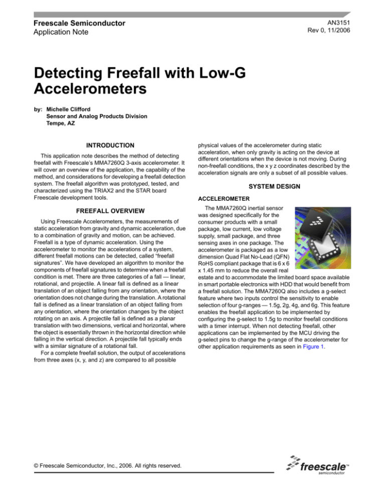
The MMA7260Q inertial sensor
was designed specifically for the
consumer products with a small
package, low current, low voltage
supply, small package, and three
sensing axes in one package. The
accelerometer is packaged as a low
dimension Quad Flat No-Lead (QFN)
RoHS compliant package that is 6 x 6
x 1.45 mm to reduce the overall real
estate and to accommodate the limited board space available
in smart portable electronics with HDD that would benefit from
a freefall solution. The MMA7260Q also includes a g-select
feature where two inputs control the sensitivity to enable
selection of four g-ranges — 1.5g, 2g, 4g, and 6g. This feature
enables the freefall application to be implemented by
configuring the g-select to 1.5g to monitor freefall conditions
with a timer interrupt. When not detecting freefall, other
applications can be implemented by the MCU driving the
g-select pins to change the g-range of the accelerometer for
other application requirements as seen in Figure 1.
Figure 1. G-Select Enables Multiple Applications with One Accelerometer
MICROCONTROLLER
If there is a dynamic change in the orientation, another freefall
algorithm will be needed.
The Freefall detection demo was implemented on a low
cost, 8-bit microcontroller with 8K of flash memory. These are
the minimum processing requirements for running the freefall
detection algorithm and sending a high/low signal to drive an
LED or Piezohorn when freefall is detected. This ensures that
freefall is quickly and reliably detected because there are no
other processes running that may take precedence over the
freefall detection algorithm. In most end products, there is a
need for more complex MCUs or DSPs. In that case the
freefall algorithm can be easily upgrade to one of these
processors.
Figure 2. Linear Freefall is Defined as a Linear
Translation to Earth’s Surface without any Dynamic
Change in Orientation
LINEAR FREEFALL
Linear freefall is the simplest of the three identified types of
falls. Linear freefall is defined as a drop when the device was
not previously moving, so there are no other forces acting on
the device. Linear freefall is independent of the original
orientation of the device. However, the requirement for linear
freefall detection is that the orientation remains during the fall.
The linear freefall algorithm entails sampling the x-, y-, and
z-axis output signals. If the acceleration on all three axes are
determined to be at 0g with a predefined margin (i.e., ±5 bits
when using an 8-bit ADC), for a set duration of time (5
samples in a row), then we are in a linear freefall condition.
300
250
200
X
Y
150
Z
100
50
10
9.8
9.56
9.31
9.07
8.82
8.58
8.33
8.09
7.6
7.84
7.35
7.11
6.86
6.62
6.37
6.13
5.88
5.64
5.39
4.9
5.15
4.66
4.41
4.17
3.92
3.68
3.43
3.19
2.7
2.94
2.45
2.21
1.96
1.72
1.47
1.23
0.98
0.74
0.49
0
0.25
0
Basic Software Algorithm Parameters
•
•
•
•
•
•
Resolution of Analog to Digital converter:
Accelerometer(s):
Processor speed/Sampling Rate:
Averaging:
0g Offset Calibration:
Operating Temperature:
8-bit (MC68HC908KX8)
MMA7260Q
50 Hz (200 samples per second)
None
YES
approx 25°C
AN3151
2
Sensors
Freescale Semiconductor
S-FACTOR
At all times, the accelerometer will sense the acceleration
of gravity. Depending on the orientation, each axis of the
accelerometer will see a range of accelerations from 1g (when
the axis is parallel to gravity) to 0g (when the axis is
perpendicular to gravity). The S-factor is a way to consider the
total acceleration acting on the device at once, acting for all
axes combined.
Sfactor =
2
2
Xout + Yout + Zout
2
When the accelerometer is held in any orientation, at least
one of the sensing axes will be parallel with the acceleration
of gravity. Therefore, at least one of the axes will be more than
0g. For example, when the accelerometer is tilted at an angle,
a portion of the acceleration of gravity will be sensed.
Therefore, the S-factor will always be equal to 1 when the
accelerometer is static.
Sfactor =
2
2
1 +0 +0
2
During freefall, all 3 sensing axes converge to 0g. Since the
S-factor is the total acceleration on all axes and all three axes
are zero, the S-factor is 0. The S-factor will only be zero when
freefall is occurring.
Sfactor =
2
2
0 +0 +0
2
AN3151
Sensors
Freescale Semiconductor
3
HEIGHT REQUIREMENTS FOR
FREEFALL DETECTION
The height requirement for detecting freefall is directly
dependent on the sampling rate of the software, the
conversion time of the ADC, and the time segment given for
sampling the freefall algorithm in the overall system. The
freefall demo algorithm samples the data from x, y, and z
output signals 256 times and takes the average for a steady
value. The conversion of an ATD signal requires between 16
and 17 ADC clock cycles of the MC68HC908KX8 to complete.
Conversion time in terms of the number of bus cycles is a
function of CGMXCLK frequency, bus frequency, the ADIV
prescaler bits, and the ADICLK bit. For example, with a
CGMXCLK frequency of 8 MHz, bus frequency of 2 MHz, and
fixed ADC clock frequency of 1 MHz, one conversion will take
between 16 and 17 µs and there will be 32 bus cycles between
each conversion. Therefore, the sample rate would be
approximately 60 kHz. However, in most freefall applications,
the fall protection mechanism is what takes over 95% of the
fall time. For example, in a Hard drive protection application,
the actual parking of the drive takes over 60 ms. Therefore,
when designing a freefall protection algorithm, the typical
height of a fall should be considered in addition to the
limitation of the mechanical protection mechanism to
determine what is more important in the solution — speed or
accuracy.
Table 1. Time in Freefall
Height of Fall
(mm)
Time of Fall
(ms)
5
31.944
10
45.175
50
101.02
100
142.86
200
202.03
300
247.44
400
285.71
500
319.44
600
349.93
700
377.96
800
404.06
900
428.57
1000
451.75
Table 2. Sampling Rate and Time to Detect Freefall
Sample/s
Samples in
Algorithm
S/Sample
TIME REQUIREMENTS FOR
FREEFALL DETECTION
200
1
0.005
5
500
1
0.002
2
The time that an object will be in freefall when dropped from
a typical drop height is useful for determining the maximum
time allowed for the total freefall protection solution. The time
required for an object to fall from a specific height is calculated
using the kinematic equations of motion. For calculating a
distance (height of the fall) with a known acceleration (gravity)
from a static height (the initial velocity equals zero), we have
the following equation:
1000
1
0.001
1
200
10
0.05
50
500
10
0.02
20
1000
10
0.01
10
200
20
0.1
100
500
20
0.04
40
1000
20
0.02
20
d = vi * t + ½ *a*t^2
= 0 + ½ *a*t^2
Since the distance is the known height of the fall and the
acceleration of gravity is a known constant, the time can be
calculated from the following translated equation:
t2 = 2d/a
______
t = [(2d)/a]
For example, if the typical height for an application is
700 mm, then the time needed for detecting freefall and
protecting the device would be less than 400 ms.
t =
=
=
=
[(2d)/a]
[ (2 x 0.070 m ) / 9.8 m/s2 ]
0.3779 seconds
400 ms
Using this equation a time table can be formed so that the
time a device is in freefall can be referenced (see Table 1)
along with the time requirement for detecting freefall (see
Table 2) to provide an understanding of how much time is
available after the detection of freefall before impact occurs.
Time to Detect
Freefall (ms)
The time it takes for a system to detect freefall is directly
related to the sampling rate of the system. If the analog to
digital converter samples at 200 times per second, as in the
Freescale Accelerometer demo board, then the system
requires 100 ms before determining a freefall condition. If the
system is able to sample at 1000 times per second, then a
freefall condition can be detected in 10 ms. Another factor in
the time required for freefall detection is the number of
samples that are used in the freefall algorithm. For a simple
linear freefall algorithm, only one sample is needed to
determine freefall. However, to include detection for rotational
and projectile freefall and increase the accuracy of freefall
detection by looking at the conditions of the device before
freefall, more samples may be needed before determining
freefall. Table 2 shows the time required to detect freefall at
the sampling rate of 200, 500, and 1000 samples per second
along with 3 different levels of detection — simple freefall
detection using 1 sample to determine freefall, and more
complex algorithms which require 10 and 20 samples before
determining freefall.
AN3151
4
Sensors
Freescale Semiconductor
RELIABILITY OF FREEFALL DETECTION
The reliability of freefall is dependent on the algorithm that
is used and the calibration of the 0g offset of the device. The
variation of the 0g offset for the MMA7260Q is shown in
Figure 3. Depending on the range of the ADC bits in the
algorithm logic, the reliability will be affected if the system is
not calibrated for 0g on all axes. Our freefall solution
recommends a 0g calibration for the highest reliability of
freefall. As seen from Figure 1, the mean of the X, Y, and Z
offset voltages is 1.654, 1.637, and 1.621, respectively. This
variation between axes can be hard coded in the software;
however, for six sigma reliability, the ranges for each axis
would need to be considered.
Distributions
X-offset
Quantiles
LSL
Target
USL
1.5 1.55 1.6 1.65 1.7 1.75 1.8
100.0% maximum
99.5%
97.5%
90.0%
quartile
75.0%
median
50.0%
quartile
25.0%
10.0%
2.5%
0.5%
minimum
0.0%
Moments
1.7034
1.7008
1.6878
1.6767
1.6665
1.6542
1.6420
1.6309
1.6220
1.6066
1.6010
Mean
Std Dev
Std Err Mean
upper 95% Mean
lower 95% Mean
N
Capability Analysis
1.6545037
0.0173212
0.001
1.6564717
1.6525357
300
Specification
Value
Portion
Lower Spec Limit
Upper Spec Limit
Spec Target
1.485
1.815
1.65
Below LSL
Above USL
Total Outside
% Actual
0.0000
0.0000
0.0000
Overall, Sigma = 0.01732
-3s Mean +3s
LSL
Target
1.5
1.6
USL
1.7
1.8
Capability
Index Lower CI
CP
CPK
CPM
CPL
CPU
3.175
3.089
3.073
3.262
3.089
Portion
Below LSL
Above USL
Total Outside
Upper CI
2.921
2.837
2.834
3.430
3.341
3.312
Percent
PPM
0.0000
0.0000
0.0000
0.0000
0.0000
0.0000
Y-offset
Quantiles
LSL
Target
USL
1.5 1.55 1.6 1.65 1.7 1.75 1.8
100.0% maximum
99.5%
97.5%
90.0%
quartile
75.0%
median
50.0%
quartile
25.0%
10.0%
2.5%
0.5%
0.0%
minimum
Moments
1.6972
1.6922
1.6741
1.6623
1.6507
1.6366
1.6242
1.6139
1.6036
1.5917
1.5916
Mean
Std Dev
Std Err Mean
upper 95% Mean
lower 95% Mean
N
Capability Analysis
1.6376483
0.0183739
0.0010608
1.6397359
1.6355607
300
Specification
Value
Portion
Lower Spec Limit
Upper Spec Limit
Spec Target
1.485
1.815
1.65
Below LSL
Above USL
Total Outside
% Actual
0.0000
0.0000
0.0000
Overall, Sigma = 0.01837
-3s Mean +3s
LSL
Target
1.5
1.6
USL
1.7
1.8
Capability
Index Lower CI
CP
CPK
CPM
CPL
CPU
2.993
2.769
2.484
2.769
3.217
Portion
Below LSL
Above USL
Total Outside
Upper CI
2.753
2.543
2.306
3.233
2.996
2.663
Percent
PPM
0.0000
0.0000
0.0000
0.0000
0.0000
0.0000
Z-offset
Quantiles
LSL
Target
USL
1.5 1.55 1.6 1.65 1.7 1.75 1.8
100.0% maximum
99.5%
97.5%
90.0%
quartile
75.0%
median
50.0%
quartile
25.0%
10.0%
2.5%
0.5%
minimum
0.0%
Moments
1.6750
1.6720
1.6610
1.6491
1.6347
1.6232
1.6074
1.5942
1.5708
1.5656
1.5648
Mean
Std Dev
Std Err Mean
upper 95% Mean
lower 95% Mean
N
Capability Analysis
1.6211368
0.0215688
0.0012453
1.6235874
1.6186862
300
Specification
Value
Portion
Lower Spec Limit
Upper Spec Limit
Spec Target
1.485
1.815
1.65
Below LSL
Above USL
Total Outside
% Actual
0.0000
0.0000
0.0000
Overall, Sigma = 0.02157
-3s
Mean
LSL
1.5
+3s
Target
1.6
USL
1.7
1.8
Capability
Index Lower CI
CP
CPK
CPM
CPL
CPU
2.550
2.104
1.526
2.104
2.996
Portion
Below LSL
Above USL
Total Outside
Upper CI
2.346
1.930
1.423
2.754
2.278
1.630
Percent
PPM
0.0000
0.0000
0.0000
0.0000
0.0000
0.0000
Figure 3. MMA7260Q 0g Offset Data
AN3151
Sensors
Freescale Semiconductor
5
Another consideration is the operating temperature of the
system. The characterization of freefall in this report was
completed at room temperature, approximately 25°C.
However, during the operation of some consumer electronics,
the temperature increased beyond room temperature, so
temperature drift may need to be considered. The operating
temperature of the MMA7260Q is in the range of -20 to 80°C.
Figure 4, Figure 5, and Figure 6 shows the temperature drift of
the MMA7260Q in the operating temperature range. The
changes in offset are small, so they should not alter the
reliability of a freefall solution. However, a system
characterization for temperature is still recommended.
100
80
Part 1
Part 2
Part 3
Part 4
Part 5
Part 6
Part 7
Part 8
Part 9
Part 10
Part 11
Part 12
Part 13
Part 14
Part 15
Part 16
Part 17
Part 18
Part 19
Part 20
Part 21
Part 22
Part 23
Part 24
60
40
Drift (mg/min)
20
0
-20
-40
-60
-80
-100
-30
-20
-10
0
10
20
30
40
50
60
70
80
90
Temperature (C)
Figure 4. X-Offset Drift Over Temp (mg/min) at VDD = 3.3 V
100
80
Part 1
Part 2
Part 3
Part 4
Part 5
Part 6
Part 7
Part 8
Part 9
Part 10
Part 11
Part 12
Part 13
Part 14
Part 15
Part 16
Part 17
Part 18
Part 19
Part 20
Part 21
Part 22
Part 23
Part 24
60
40
Drift (mg/min)
20
0
-20
-40
-60
-80
-100
-30
-20
-10
0
10
20
30
40
50
60
70
80
90
Temperature (C)
Figure 5. Y-Offset Drift Over Temp (mg/min) at VDD = 3.3 V
100
80
Part 1
Part 2
Part 3
Part 4
Part 5
Part 6
Part 7
Part 8
Part 9
Part 10
Part 11
Part 12
Part 13
Part 14
Part 15
Part 16
Part 17
Part 18
Part 19
Part 20
Part 21
Part 22
Part 23
Part 24
60
40
Drift (mg/min)
20
0
-20
-40
-60
-80
-100
-30
-20
-10
0
10
20
30
40
50
60
70
80
90
Temperature (C)
Figure 6. Z-Offset Drift Over Temp (mg/min) at VDD = 3.3 V
AN3151
6
Sensors
Freescale Semiconductor
SHOCK PROTECTION IN ADDITION TO
FREEFALL PROTECTION
Freefall detection is typically used for hard drive protection.
However, freefall protection does not include protection from
shock, which would not put the device into a freefall mode.
Shock includes banging of the product itself, or using an
external device to apply shock to the product, or excessive
shaking of the product. Shock protection would have to be
added in addition to freefall protection to ensure full protection
on a hard drive during all types of excessive handing.
Table 3. Testing of the RD3112MMA7260Q
Trial
Orientation
Height of
Fall
Freefall
Detected
1
X-axis =1g
15 cm
Yes
2
X-axis =1g
10 cm
Yes
3
X-axis =1g
5 cm
Yes
4
Y-axis =1g
15 cm
Yes
5
Y-axis =1g
10 cm
Yes
6
Y-axis =1g
5 cm
Yes
7
Z-axis =1g
15 cm
Yes
8
Z-axis =1g
10 cm
Yes
9
Z-axis =1g
5 cm
Yes
10
X-axis = -1g
15 cm
Yes
11
X-axis = -1g
10 cm
Yes
12
X-axis = -1g
5 cm
Yes
13
Y-axis = -1g
15 cm
Yes
14
Y-axis = -1g
10 cm
Yes
15
Y-axis = -1g
5 cm
Yes
16
Z-axis = -1g
15 cm
Yes
17
Z-axis = -1g
10 cm
Yes
18
Z-axis = -1g
5 cm
Yes
AN3151
Sensors
Freescale Semiconductor
7
How to Reach Us:
Home Page:
www.freescale.com
Web Support:
http://www.freescale.com/support
USA/Europe or Locations Not Listed:
Freescale Semiconductor, Inc.
Technical Information Center, EL516
2100 East Elliot Road
Tempe, Arizona 85284
+1-800-521-6274 or +1-480-768-2130
www.freescale.com/support
Europe, Middle East, and Africa:
Freescale Halbleiter Deutschland GmbH
Technical Information Center
Schatzbogen 7
81829 Muenchen, Germany
+44 1296 380 456 (English)
+46 8 52200080 (English)
+49 89 92103 559 (German)
+33 1 69 35 48 48 (French)
www.freescale.com/support
Japan:
Freescale Semiconductor Japan Ltd.
Headquarters
ARCO Tower 15F
1-8-1, Shimo-Meguro, Meguro-ku,
Tokyo 153-0064
Japan
0120 191014 or +81 3 5437 9125
support.japan@freescale.com
Asia/Pacific:
Freescale Semiconductor Hong Kong Ltd.
Technical Information Center
2 Dai King Street
Tai Po Industrial Estate
Tai Po, N.T., Hong Kong
+800 2666 8080
support.asia@freescale.com
For Literature Requests Only:
Freescale Semiconductor Literature Distribution Center
P.O. Box 5405
Denver, Colorado 80217
1-800-441-2447 or 303-675-2140
Fax: 303-675-2150
LDCForFreescaleSemiconductor@hibbertgroup.com
AN3151
Rev. 0
11/2006
Information in this document is provided solely to enable system and software
implementers to use Freescale Semiconductor products. There are no express or
implied copyright licenses granted hereunder to design or fabricate any integrated
circuits or integrated circuits based on the information in this document.
Freescale Semiconductor reserves the right to make changes without further notice to
any products herein. Freescale Semiconductor makes no warranty, representation or
guarantee regarding the suitability of its products for any particular purpose, nor does
Freescale Semiconductor assume any liability arising out of the application or use of any
product or circuit, and specifically disclaims any and all liability, including without
limitation consequential or incidental damages. “Typical” parameters that may be
provided in Freescale Semiconductor data sheets and/or specifications can and do vary
in different applications and actual performance may vary over time. All operating
parameters, including “Typicals”, must be validated for each customer application by
customer’s technical experts. Freescale Semiconductor does not convey any license
under its patent rights nor the rights of others. Freescale Semiconductor products are
not designed, intended, or authorized for use as components in systems intended for
surgical implant into the body, or other applications intended to support or sustain life,
or for any other application in which the failure of the Freescale Semiconductor product
could create a situation where personal injury or death may occur. Should Buyer
purchase or use Freescale Semiconductor products for any such unintended or
unauthorized application, Buyer shall indemnify and hold Freescale Semiconductor and
its officers, employees, subsidiaries, affiliates, and distributors harmless against all
claims, costs, damages, and expenses, and reasonable attorney fees arising out of,
directly or indirectly, any claim of personal injury or death associated with such
unintended or unauthorized use, even if such claim alleges that Freescale
Semiconductor was negligent regarding the design or manufacture of the part.
Freescale™ and the Freescale logo are trademarks of Freescale Semiconductor, Inc.
All other product or service names are the property of their respective owners.
© Freescale Semiconductor, Inc. 2006. All rights reserved.


