MasteringPhysics: Assignment Print View
advertisement

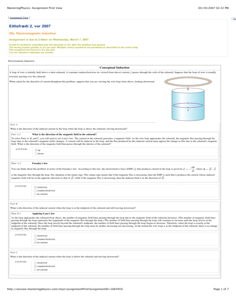
MasteringPhysics: Assignment Print View 04/19/2007 02:22 PM [ Assignment View ] [ Pri Eðlisfræði 2, vor 2007 29a. Electromagnetic Induction Assignment is due at 2:00am on Wednesday, March 7, 2007 Credit for problems submitted late will decrease to 0% after the deadline has passed. The wrong answer penalty is 2% per part. Multiple choice questions are penalized as described in the online help. The unopened hint bonus is 2% per part. You are allowed 4 attempts per answer. Electromanetic Induction Conceptual Induction A loop of wire is initially held above a short solenoid. A constant counterclockwise (as viewed from above) current passes through the coils of the solenoid. Suppose that the loop of wire is steadily lowered, passing over the solenoid. When asked for the direction of current thoughout this problem, suppose that you are viewing the wire loop from above, looking downward. Part A What is the direction of the induced current in the loop when the loop is above the solenoid, moving downward? Part A.1 What is the direction of the magnetic field in the solenoid? To solve Parts A, B, and C, you will need to use Lenz's law. The current in the solenoid generates a magnetic field. As the wire loop approaches the solenoid, the magnetic flux passing through the loop (due to the solenoid's magnetic field) changes. A current will be induced in the loop, and the flux produced by this induced current must oppose the change in flux due to the solenoid's magnetic field. What is the direction of the magnetic field that passes through the interior of the solenoid? ANSWER: Hint A.2 up down Faraday's law You can think about this problem in terms of the Faraday's law. According to this law, the electromotive force (EMF) that produces current in the loop is given by , where is the magnetic flux through the loop. Pay attention at the minus sign. This minus sign means that if the magnetic flux is increasing, then the EMF is such that it produces the current whose induced magnetic field will be in the opposite direction to that of , while if the magnetic flux is decreasing, then the induced field is in the direction of . ANSWER: clockwise counterclockwise no current Part B What is the direction of the induced current when the loop is at the midpoint of the solenoid and still moving downward? Hint B.1 Applying Lenz's law As the loop approaches the solenoid from above, the number of magnetic field lines passing through the loop due to the magnetic field of the solenoid increases. (The number of magnetic field lines passing through the loop represents the magnitude of the magnetic flux through the loop.) The number of field lines passing through the loop will continue to increase until the loop arrives at the midpoint of the solenoid. Once the loop travels beyond the solenoid's midpoint, the number of field lines passing through the loop begins to decrease. Therefore, when the loop is exactly at the midpoint of the solenoid, the number of field lines passing through the loop must be neither increasing nor decreasing. At the instant the wire loop is at the midpoint of the solenoid, there is no change in magnetic flux through the loop. ANSWER: clockwise counterclockwise no current Part C What is the direction of the induced current when the loop is below the solenoid and moving downward? ANSWER: clockwise counterclockwise no current http://session.masteringphysics.com/myct/assignmentPrint?assignmentID=1064959 Page 1 of 7 MasteringPhysics: Assignment Print View 04/19/2007 02:22 PM Faraday's Law Introduction to Faraday's Law Learning Goal: To understand the terms in Faraday's law for magnetic induction of electric fields, and contrast these fields with those produced by static charges. Faraday's law describes how electric fields and electromotive forces are generated from changing magnetic fields. It relates the line integral of the electric field around a closed loop to the change in the total magnetic field integral across a surface bounded by that loop: , where is the line integral of the electric field, and the magnetic flux is given by , where is the angle between the magnetic field and the local normal to the surface bounded by the closed loop. Direction: The line integral and surface integral reverse their signs if the reference direction of applies here: If the thumb of your right hand points along , then the fingers point along or is reversed. The right-hand rule . You are free to take the loop anywhere you choose, although usually it makes sense to choose it to lie along the path of the circuit you are considering. Part A Consider the direction of the electric field in the figure. Assume that the magnetic field points upward, as shown. Under what circumstances is the direction of the electric field shown in the figure correct? Hint A.1 How to approach the problem There are two approaches: One approach is to realize that the electric field would produce a current in the same direction as the field if there were a wire present. Find the magnetic field due to this (imaginary) current using the right-hand rule. The magnetic field produced by this current must oppose the change in the original magnetic field. You should be able to tell what the change is. The other approach is more mathematical. Choose a direction for and . Suppose is in the direction of the electric field shown. Then has the same direction as that of the magnetic field shown. The left-hand side of Faraday's equation is positive, and so is the magnetic flux. However, since the left-hand side is positive, the change in flux should be negative. What must have happened to the field? ANSWER: always if increases with time if decreases with time depending on whether your right thumb is pointing up or down Part B Now consider the magnetic flux through a surface bounded by the loop. Which of the following statements about this surface must be true if you want to use Faraday's law to relate the magnetic flux to the line integral of the electric field around the loop? ANSWER: The surface must be the circular disk in the middle of the loop. The surface must be perpendicular to the magnetic field at each point. The surface can be any surface whose edge is the loop. The surface can be any surface whose edge is the loop as long as no magnetic field line passes through it more than once. You are free to take any surface bounded by the loop as the surface over which to evaluate the integral. The result will always be the same, owing to the continuity of magnetic field lines (they never start or end anywhere, since there are no magnetic charges). It is important to understand the vast differences between electric fields produced by changing magnetic fields via Faraday's law and the more familiar electric fields produced by charges via Coulomb's law. Here are some short questions that illustrate these differences. Part C When can an electric field be measured at any point from the force on a stationary test charge at that point? Hint C.1 Force on a stationary charge Recall that the total force on a charge is . If the charge is stationary, i.e., ANSWER: , then the force reduces to . only if the field is generated by the coulomb field of static charges only if the field is generated by a changing magnetic field http://session.masteringphysics.com/myct/assignmentPrint?assignmentID=1064959 Page 2 of 7 MasteringPhysics: Assignment Print View 04/19/2007 02:22 PM only if the field is generated by a changing magnetic field no matter how the field is generated In fact, this operation defines an electric field. Similarly, if the test charge is moving, it will measure magnetic fields. Part D When can an electric field that does not vary in time arise? ANSWER: only if the field is generated by a coulomb field of static charges only if the field is generated by a changing magnetic field in either of the above two cases Electric fields never vary in time; otherwise, a charge could gain energy from the field. Part E When will the integral ANSWER: around any closed loop of the projection of the electric field along that loop be zero? only if the field is generated by the coulomb field of static charges only if the field is generated by the coulomb field of static charges or a constant current only if the field is generated by a changing magnetic field however the field is generated The loop integral is always zero; otherwise, a charge moving around the loop would gain energy. The electric field generated by a static charge or a constant current always has zero loop integral. A constant current is a continuous line of evenly-spaced charges moving with constant velocity. An electric field generated by any other configuration of moving charges (moving through the loop) would have a non-zero loop integral. Here is a simple quantitative problem that uses Faraday's law. Part F A cylindrical iron rod of infinite length with cross-sectional area magnetic field inside that varies according to Hint F.1 is oriented with its axis of symmetry coincident with the z axis of a cylindrical coordinate system as shown in the figure. It has a . Find the theta component of the electric field at distance from the z axis, where is larger than the radius of the rod. Selecting the loop You want to find , but Faraday's law determines only an integral of the field. Therefore, you must pick the loop around which you will integrate in such a way that it involves only one value of and has a constant projection of Part F.2 Find the magnetic flux Faraday's law states that Hint F.2.a along it. Such a loop is a circle with fixed (at any z, since the rod extends infinitely in the z direction). . Therefore, to find the electric field you must first find the magnetic flux. What is the magnetic flux at time ? The flux integral The flux integral for a constant field is the product of the magnitude of the perpendicular magnetic field and the area over which the integral is evaluated. Express your answer in terms of the magnetic field variables ANSWER: Part F.3 , , and . = Finding the EMF from Faraday's law From the previous part, you found that Express your answer in terms of ANSWER: Hint F.4 and , . According to Faraday's law, , . Use your equation for to find the EMF predicted by Faraday's law. , , and any necessary constants. = Help from symmetry The rod extends along the entire z axis, so the electric field cannot depend on . Since the rod is cylindrically symmetric, the field cannot depend on field is a function only of either. Thus, the component of the electric . http://session.masteringphysics.com/myct/assignmentPrint?assignmentID=1064959 Page 3 of 7 MasteringPhysics: Assignment Print View Part F.5 04/19/2007 02:22 PM Find the EMF in terms of By definition, the EMF around a loop is given by Hint F.5.a . The dot product means that you need consider only the component of parallel to . Find the relationship between and . The component of the field along the loop Since the loop is a circle with constant Express in terms of ANSWER: but varying , the component of the electric field is the component along the loop. , quantities given in the introduction to this part, and familiar constants. = Answer not displayed Express your answer in terms of ANSWER: , , , , and any needed constants such as , , and . = Electric Field Due to Increasing Flux Learning Goal: To work through a straightforward application of Faraday's law to find the EMF and the electric field surrounding a region of increasing flux Faraday's law describes how electric fields and electromotive forces are generated from changing magnetic fields. This problem is a prototypical example in which an increasing magnetic flux generates a finite line integral of the electric field around a closed loop that surrounds the changing magnetic flux through a surface bounded by that loop. A cylindrical iron rod with cross-sectional area is oriented with its symmetry axis coincident with the z axis of a cylindrical coordinate system as shown. It has a uniform magnetic field inside that varies according to . In other words, the magentic field is always in the positive z direction, and it has no other components. For your convenience, we restate Faraday's law here: , where the electric field, and the magnetic flux is given by , where is the line integral of is the angle between the magnetic field and the local normal to the surface bounded by the closed loop. Direction: The line integral and surface integral reverse their signs if the reference direction of applies here: If the thumb of your right hand is taken along , then the fingers point along or is reversed. The right-hand rule . You are free to take the loop anywhere you choose, although usually it makes sense to choose it to lie along the path of the circuit you are considering. Part A Find , the electromotive force (EMF) around a loop that is at distance from the z axis, where is restricted to the region outside the iron rod as shown. Take the direction shown in the figure as positive. Hint A.1 Selecting the loop Hint not displayed Part A.2 Find the magnetic flux Part not displayed Express in terms of ANSWER: , , , , and any needed constants such as , , and . = Answer not displayed Part B Due to the cylindrical symmetry of this problem, the induced electric field can depend only on the distance from the z axis, where is restricted to the region outside the iron rod. Find this field. Part B.1 Calculate the line integral Part not displayed Hint B.2 The z and r components of the electric field Hint not displayed Express in terms of quantities given in the introduction (and constants), using the unit vectors in the cylindrical coordinate system, , , and . ANSWER: = Answer not displayed Motion-Induced EMF's Motion-Induced Electric Fields and Motional EMF http://session.masteringphysics.com/myct/assignmentPrint?assignmentID=1064959 Page 4 of 7 MasteringPhysics: Assignment Print View 04/19/2007 02:22 PM Learning Goal: To understand that the motion of a conductor through a magnetic field generates a perpendicular electric field. A conducting rod of length end of the rod at is moved at a constant velocity through a uniform magnetic field . This field runs perpendicularly out of the page. The end of the rod at is labeled a, and the is labeled b. Part A As a result of the motion through the magnetic field, a charge in the rod will experience a force : the usual part of the Lorentz force for charges moving through magnetic fields. This force will push the charge in the rod, and hence this force will be an electromotive force (EMF). For now, we shall say that the force that moves the charges is due to an induced electric field , which will enable us to calculate the EMF. The fact that there is an induced electric field at all is rather subtle, because there is no closed loop that encloses some changing flux. Therefore, a method that does not involve Faraday's law must be used to solve this motional EMF problem. In fact, this problem is a good introduction to some of the ideas behind Faraday's law. Find the y component of the induced electric field . Part A.1 Find the force on a charge due to motion in the magnetic field Part not displayed Part A.2 Find an equivalent electric field Part not displayed Express your answer in terms of the variables given in the problem introduction. ANSWER: = Answer not displayed Part B Part not displayed Part C There is a big complication in measuring the EMF generated by the moving rod: The wires that connect the meter to the rod also move through the magnetic field, and therefore, there is an electromotive force for them also. This is a general problem: A voltmeter can measure the EMF produced only in a closed loop around the circuit. In general, the EMF caused by the motion of a rod through a uniform magnetic field will be canceled by the opposite EMF induced by the motion of the rest of the circuit through this same uniform field. The only way to get a nonzero voltmeter reading is to make the field nonuniform, for example, such that the bar is moving through a region of nonzero field, but the rest of the circuit is (temporarily) moving in a region of zero field. For example, consider the arrangement shown in the figure for measuring the EMF in the moving rod using a voltmeter. In this arrangement, only for and . The hookup wires and voltmeter will have to move with the rod; they are rigid and of the dimensions and shape shown. The physical setup is that shown at the end of Part B. Which graph shown best represents the magnitude of that will be measured by the voltmeter? Take to be the moment pictured in the diagram. Hint C.1 How to approach the problem Hint not displayed Part C.2 Describe the EMF when only the rod moves through the field Part not displayed Part C.3 Describe the EMF when the whole circuit is moving through the field Part not displayed ANSWER: Answer not displayed Part D Part not displayed http://session.masteringphysics.com/myct/assignmentPrint?assignmentID=1064959 Page 5 of 7 MasteringPhysics: Assignment Print View 04/19/2007 02:22 PM Rail Gun This problem explores how a current-carrying wire can be accelerated by a magnetic field. You will use the ideas of magnetic flux and the EMF due to change of flux through a loop. Note that there is an involved follow-up part that will be shown once you have found the answer to Part B. Part A A conducting rod is free to slide on two parallel rails with negligible friction. At the right end of the rails, a voltage source of strength in series with a resistor of resistance makes a closed circuit together with the rails and the rod. The rails and the rod are taken to be perfect conductors. The rails extend to infinity on the left. The arrangement is shown in the figure. There is a uniform magnetic field of magnitude , pervading all space, perpendicular to the plane of rod and rails. The rod is released from rest, and it is observed that it accelerates to the left. In what direction does the magnetic field point? Hint A.1 The force on a conducting rod due to a magnetic field There is a force on the rod because a current is flowing through it. Hence charges are moving perpendicular to the magnetic field. The rod experiences a force Hint A.2 , which is given by . The direction of the magnetic field Use the right-hand rule with the cross product: Take your right hand and point with your index finger in the direction of the rail's motion, and point your middle finger in the direction of . Your thumb will then point in the direction of the magnetic field. ANSWER: into the plane of the figure out of the plane of the figure Part B Assuming that the rails have no resistance, what is the most accurate qualitative description of the motion of the rod? Hint B.1 Lenz's law An EMF is induced in the circuit due to the change in magnetic flux through it. But will this EMF increase the current through the loop or decrease it by opposing the voltage coming from the source? Lenz's law states that induced currents will always flow in such a way that they oppose the change in flux that caused them. Hint B.2 Appyling Lenz's law to this problem Let us apply Lenz's law here. We want to find the direction of the induced current. The change in flux that induced this current is caused by the motion of the rod, which in turn is caused by the current flowing around the circuit due to the voltage source. The induced current works against that source current, and reduces it. Alternatively, one could say that the induced EMF opposes the voltage from the source. Hint B.3 The velocity of the rod The higher the velocity of the rod, the higher the induced EMF, and the lower the current flowing through the loop. But the force accelerating the rod is proportional to the current. Hence the acceleration goes down as the velocity goes up. The velocity cannot increase beyond the point at which the induced EMF is equal and opposite to . ANSWER: The rod will accelerate but the magnitude of the acceleration will decrease with time; the velocity of the rod will approach but never exceed a certain terminal velocity. Under these idealized conditions the rod will experience constant acceleration and the velocity of the rod will increase indefinitely. The rod will accelerate indefinitely with acceleration proportional to its (increasing) velocity. Part C What is the acceleration Part C.1 of the rod? Take Find the induced EMF To determine the current, we need the EMF motion of the rod will change Express to be the mass of the rod. according to in terms of the velocity ANSWER: Part C.2 induced by the change in magnetic flux . What is the EMF , the separation of the rails through the current loop of area . Faraday's law states that . The ? , and the magnetic field . = Find the current in the rod We can find the current through the rail by using Kirchhoff's rule for a closed circuit: Express your answer in terms of , where is the induced EMF. What is the current ? and other given quantities. ANSWER: http://session.masteringphysics.com/myct/assignmentPrint?assignmentID=1064959 Page 6 of 7 MasteringPhysics: Assignment Print View ANSWER: Part C.3 04/19/2007 02:22 PM = Find the acceleration of the rod To find the acceleration , we need the force on the rod. We have already determined its direction. The magnitude of this force is given in Part A.i. Write down an expression for , using Newton's second law. Expres your answer in terms of mass ANSWER: , current , , and . = Express your answer as a function of ANSWER: , , the velocity of the rod , , , and the mass of the rod . = Making the substitution , you obtain the dfferential equation , which you can solve to find the velocity of the rod as a function of time: . To achieve a high acceleration, which is necessary for a useful gun, a magnetic field of large magnitude and a high voltage are advantageous. Part D What is the terminal velocity Part D.1 reached by the rod? Find an expression for the terminal velocity Part not displayed ANSWER: = A larger magnetic field increases the acceleration of the rod, but lowers the terminal velocity: a trade-off for rail gun engineers! Summary 3 of 5 problems complete (44.22% avg. score) 9.55 of 12 points http://session.masteringphysics.com/myct/assignmentPrint?assignmentID=1064959 Page 7 of 7


