PHYS 110A - HW #9
advertisement
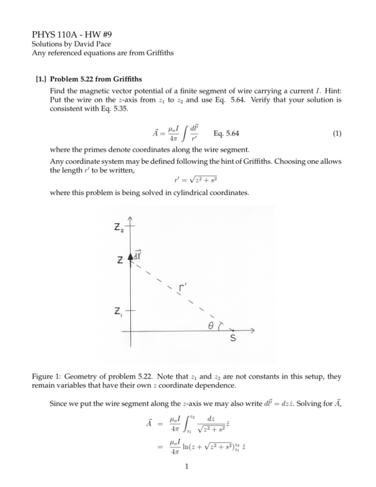
PHYS 110A - HW #9 Solutions by David Pace Any referenced equations are from Griffiths [1.] Problem 5.22 from Griffiths Find the magnetic vector potential of a finite segment of wire carrying a current I. Hint: Put the wire on the z-axis from z1 to z2 and use Eq. 5.64. Verify that your solution is consistent with Eq. 5.35. ~ = µo I A 4π Z d~l0 r0 Eq. 5.64 (1) where the primes denote coordinates along the wire segment. Any coordinate system may be defined following the hint of Griffiths. Choosing one allows the length r0 to be written, √ r 0 = z 2 + s2 where this problem is being solved in cylindrical coordinates. Figure 1: Geometry of problem 5.22. Note that z1 and z2 are not constants in this setup, they remain variables that have their own z coordinate dependence. ~ Since we put the wire segment along the z-axis we may also write d~l0 = dz ẑ. Solving for A, Z µo I z2 dz ~ √ A = ẑ 2 4π z1 z + s2 √ µo I = ln(z + z 2 + s2 )zz21 ẑ 4π 1 # " p 2 2 + s z z + µ I ~ = o ln 2 p 2 ẑ A 4π z1 + z12 + s2 (2) We need to show that this agrees with Eq. 5.35, B= µo I (sin θ2 − sin θ1 ) 4πs Eq. 5.35 (3) where this is already written in cylindrical coordinates. ~ Write out the magnetic field from A, ~ = ∇ ~ ×A ~ B = 1 ∂Az ∂Az ŝ − φ̂ s ∂φ ∂s = − ∂Az φ̂ ∂s ~ has only a z component and that component has no where this accounts for the fact that A φ dependence. ~ is found by way of algebra. Now B # 1 z22 + s2 )(−1) 21 2s 2s p p p 2 p + φ̂ 2 2 2 2 2 (z1 + z1 + s ) z1 + s (z1 + z12 + s2 ) z22 + s2 " # s µo I s p p p p − φ̂ = − 4π (z2 + z22 + s2 ) z22 + s2 (z1 + z12 + s2 ) z12 + s2 ~ = − µo I B 4π " p z 2 + s2 p 1 z2 + z22 + s2 z1 + #" (z2 + p The next step involves multiplying each term by the quantity (unity) necessary to get a difference of squares in the denominator. " # p p 2 2 2 2 z − z + s z − z + s µ Is 1 2 o 2 1 ~ =− p p B − φ̂ 4π (z22 − (z22 + s2 )) z22 + s2 (z12 − (z12 + s2 )) z12 + s2 The geometry of the problem allows us to write, z1 sin θ1 = p 2 z1 + s2 z2 sin θ2 = p z22 + s2 Getting back to the matter at hand, " # p p 2 2 2 2 ~ = − µo Is z2 − pz2 + s − z1 − pz1 + s B φ̂ 4π (−s2 )) z22 + s2 (−s2 )) z12 + s2 " # µo I z z1 p 2 = −1− p 2 + 1 φ̂ 2 2 4πs z2 + s z1 + s2 2 (4) ~ = µo I [sin θ2 − sin θ1 ]φ̂ B 4πs (5) and this agrees with Eq. 5.35. [2.] Problem 5.29 from Griffiths Find the magnetic field inside a uniformly charged sphere of total charge Q and radius R that is rotating at a constant angular velocity ω. Use the results of example 5.11 in Griffiths. ~ of a rotating spherical shell. We will adapt this Example 5.11 gives the vector potential, A ~ to determine the magnetic solution to a rotating solid sphere and then use the value of A ~ =∇ ~ × A. ~ field through B Example 5.11 determines the potential of the shell to be, ~ in = µo Rωσ r sin θφ̂ A 3 (6) µo ωσR4 sin θ ~ Aout = φ̂ 3r2 (7) The R’s in (6) and (7) transform to (r0 )’s for our present problem. This is because we are interested in a solid sphere while the R represents the radius of the shell. The other substitution has to do with the surface charge density now being written as a volume charge density. Qtotal = σda = ρdτ σr2 sin θ dθ dφ = ρr2 sin θ dr dθ dφ σ = ρr2 sin θ dr dθ dφ r2 sin θ dθ dφ = ρdr This means that ex. 5.11 represents a differential element of the vector potential for a complete sphere. There is one added difficulty. Each shell, as we integrate over the solid sphere, ~ that consists of its own A ~ inside and its A ~ that is outside has a contribution to the final A of the shell but still inside the sphere. For instance, the shell of radius R/2 has the entire vector potential that is inside of it also inside the complete sphere. However, there is also a part of the potential of this shell that is outside of the shell itself but still inside the complete sphere (i.e. it is possible to be outside the shell but still inside R). ~ in and A ~ out from Finding the vector potential inside the solid shell must take into account A 3 each shell. This is stated mathematically as, Z R Z r µ ω µ ω o o 0 0 ~ = r sin θφ̂ ρr dr + 2 sin θφ̂ ρ(r0 )4 dr0 A 3 3r r 0 5 µo ωρ r sin θ 2 sin θ r = (R − r2 )φ̂ + 2 φ̂ 3 2 r 5 µo ωρ 3r2 2 = sin θ r R − φ̂ 6 5 Notice that the original r from ex. 5.11 was not included inside the integral. This r is a generalized coordinate variable, not a variable directly related to the sphere’s geometry. It is a difference between the primed and unprimed coordinates again. The r that is left out of the integral represents generic space while the r0 inside the integral represents the ~ would be a sphere itself. Also, if we included this r in the integral then our solution for A ~ inside would be zero. Physical intuition should tell us that this cannot constant and the B be the case. ~ in using B ~ = ∇× ~ A. ~ First, ρ must be converted Now we solve for the magnetic field inside, B to some value given by the problem. The problem only gives a total charge, not a charge density. Express the ρ used above in terms of the total charge given, 4 Qtotal = ρ πR3 3 3Q (8) 4πR3 Now for the final answer. In the first step I am only keeping those terms of the curl that ~ φ since all the other components are zero. I also factor out the constants from A ~ involve A immediately. 3r2 1 ∂ 3r2 1 ∂ µo ωρ 2 2 ~ θ̂ B = sin θ · sin θr R − r̂ − r · sin θr R − 6 r sin θ ∂θ 5 r ∂r 5 3r2 2 r R − 3 5 12r µo ωρ sin θ = 2 sin θ cos θ r̂ − 2rR2 − θ̂ 6 r sin θ r 5 ρ= µo ωρ 3r2 6r2 2 2 = cos θ R − r̂ − sin θ R − θ̂ 3 5 5 ~ in terms of the total charge, Q, given, Finally, using (8) we can write B µo ωQ 3r2 6r2 2 2 ~ Bin = cos θ R − r̂ − sin θ R − θ̂ 4πR3 5 5 (9) [3.] Problem 5.36 from Griffiths Find the magnetic dipole moment of the spinning spherical shell in example 5.11 from Griffiths. Show that for points r > R the potential is that of a perfect dipole. 4 As discussed in class (March 12, 2004), Griffiths expects students to employ a certain method for solving these types of problems based on how he has presented the magnetic dipole moment. Professor Carter discussed another method in class so both methods are used here to solve this problem. Method One Break the spinning shell into a series of infinitesimal rings. In this case the differential element of the magnetic dipole moment is given by, dm ~ = dI ~a (10) The differential element on the right hand side of (10) must be for the current because the area vector of any individual ring is, ~a = πl2 ẑ = π(r sin θ)2 ẑ ~a = πr2 sin2 θẑ (11) where l is the radius of the ring. The direction ẑ is determined by the orientation of the sphere and its rotation and can therefore be set to whatever value we want. To find dI we need to write out the current in an individual ring. This is determined using the surface current density. dI = K dL where dL is the θ̂ component of the spherical length dl = σv(r dθ) = σ|~ω × ~r|r dθ = σωr2 sin θ dθ dm ~ = πσωR4 sin3 θ dθ (12) where I have taken into account the fact that this is a shell so r = R. The magnetic dipole moment is found through an integration of dm, ~ Z π sin3 θ dθ ẑ m ~ = πσωR4 0 π 1 2 4 ẑ = πσωR − cos θ sin θ + 2 3 0 m ~ = 5 4πσωR4 ẑ 3 (13) Method Two The magnetic dipole moment may be written as, I 1 ~ da m ~ = ~r × K 2 (14) ~ From Method One and the example itself we know K, ~ = σωR sin θφ̂ K (15) Start working out the integral, note that ~r = Rr̂, I 1 m ~ = Rr̂ × (σωR sin θ)φ̂da 2 I σωR2 sin θ(−θ̂)da = 2 Stop here to make use of a simplification. Replace θ̂ with, θ̂ = cos θ cos φx̂ + cos θ sin φŷ − sin θẑ (16) Now, just as in example 5.11, the integral is taken over the da element and therefore ranges from 0 < φ < 2π. This means that the integral over φ of the sinusoidal terms in (16) will be zero. Replacing the θ̂ term in the expression for m ~ amounts to keeping only the ẑ component. Making use of this fact, along with writing out the da element gives, I σωR2 sin θ(sin θẑ)(R2 sin θ dθ dφ)ẑ m ~ = 2 Z π σωR4 = (2π) sin3 θ dθẑ 2 0 From this point the solution follows Method One. The answer will be the same as (13). The next part of this problem is to show that the potential of this sphere is exactly that of a magnetic dipole for points outside of the shell. The vector potential of a magnetic dipole is, ~ dip (~r) = µo m sin θ φ̂ A Eq. 5.85 (17) 4πr2 Inserting the solution for m found previously we have, µo sin θ 4πσωR4 ~ A = φ̂ 4πr2 3 µo σωR4 = sin θφ̂ 3r2 This potential exactly matches the solution for the potential outside the spinning shell as given by Eq. 5.67 in example 5.11. This potential is then only the dipole contribution and therefore requires that all higher orders are zero. 6 [4.] Problem 5.37 from Griffiths Find the exact magnetic field a distance z above the center of a square loop of current. Let the sides of the equare be of length w and the current be I. Verify that this reduces to the field of a dipole, of appropriate dipole moment, for the condition z w. For each individual side the expression for the magnetic field a distance s away has been given previously, µo I (sin θ2 − sin θ1 ) Eq. 5.35 (18) B= 4πs For this problem we will adjust the values of s and θi appropriately, and then take into consideration the components of the magnetic field that cancel each other. To begin I define the current in the loop to be in such a direction that the net magnetic field on the center axis will be in the ẑ direction. ~ shown is due to the current element Figure 2: Diagram of problem 5.37. The magnetic field, B, on the left side (the current is coming out of the page). This drawing is not entirely correct because it improperly deals with the three-dimensional nature of the problem. Please note the mathematical statements in place of this figure. The substitutions for s and sin θi are then, r w2 s= + z2 4 w sin θ2 = q 2 2 w2 + z 2 (19) The field at z due to one segment of the square loop becomes (noting that symmetry allows 7 sin θ1 = − sin θ2 , µo I B = 4π w2 4 4π w2 = 4 w w + q 1/2 q 2 w w2 2 2 + z2 2 2 +z 2 2 +z µo Iw 1/2 w2 + z2 2 + z2 1/2 The total field at z is four times this value because there are four segments, Btot = π w2 4 + z2 µo Iw 1/2 w2 2 + z2 1/2 (20) This is not the final magnetic field at z however, because the horizontal components will cancel. Only the component along the z axis will remain. This component may be taken out of the total expression above using Bz = Btot sin α, where α is the angle between Btot and the horizontal axis. This angle can be written in terms of parameters we already know, sin α = w 2 w2 4 + z2 1/2 (21) So the magnetic field at z is given by, ~z = B 2π w2 4 µo Iw2 2 1/2 ẑ + z 2 w2 + z 2 (22) To show that this reduces to the field of a dipole on the axis (for z w) we first write out the dipole field. This field is given by Eq. 5.86 and for the z axis we may substitute θ = 0 and r̂ = ẑ. ~ dip = µo m ẑ (23) B 2πz 3 Our solution in (22) reduces for the case of z w, µo Iw2 ẑ 2π(z 2 )3/2 ~ ≈ B µo Iw2 ẑ 2πz 3 = These expressions will be equivalent if m = Iw2 . Since this is a simple loop we know that m = I~a and ~a = w2 ẑ, so it is shown that these are equivalent expressions. Far away on the z axis the field produced by this square current loop is that of a dipole. [5.] Problem 6.1 from Griffiths Reference figure 6.6 in Griffiths. Find the torque on the square loop due to the circular loop. Assume that r a, b. If the square loop is free to rotate, then what is its equilibrium orientation? 8 The torque on the square loop is given by, ~ =m ~ N ~ ×B (24) ~ is the magnetic field where m ~ is the magnetic dipole moment of the square loop and B at the square loop that is generated by the circular loop (i.e. once again this is a situation ~ considered cannot be caused where an object cannot exert a force on itself, therefore the B by the square loop if we want to find the resultant force on that loop). The circular loop produces a dipole field (this is more accurately true at the square loop since it is given in the problem to be far away) that may be written in coordinate-free form as, ~ dip = µo I [3(m ~ · r̂)r̂ − m] ~ Eq. 5.87 (25) B 4πr3 Even before declaring coordinates for this problem it can be seen that m ~ ⊥ r̂ since r̂ points toward the square loop. This means that m ~ · r̂ = 0 and the magnetic field produced by the circular loop at the square loop is given by, µo [−m] ~ 4πr3 ~ dip = B −µo Ia2 ẑ 4r3 = where in the last step I have used m ~ circ = Iπa2 and defined coordinates. Let the magnetic dipole moment of the circular loop point in the ẑ direction and the dipole moment of the square loop point in the x̂ direction. This allows us to write the dipole moment of the square loop as m ~ sq = Ib2 x̂. The torque is, ~ = m ~ dip N ~ sq × B µo Ia2 = (Ib ) − 4r3 2 = x̂ × ẑ µ o I 2 a2 b 2 ŷ 4r3 With the chosen coordinates the ŷ direction is into the page. The right-hand rule then shows that the rotation of the square loop will be such that m ~ sq points in the −ẑ. This equilibrium position aligns m ~ sq with the magnetic field it sees, as should be expected. [6.] Problem 6.5 from Griffiths A uniform current density J~ = Jo ẑ fills a slab centered on the yz-plane and extending from x = −a to x = a. A magnetic dipole, m ~ = mo x̂ is located at the origin. (a) Find the force on the dipole using Eq. 6.3. (b) Find the force on the dipole if it is given by m ~ = mo ŷ. 9 ~ p · E) ~ and F~ = (~p · ∇) ~ E ~ are equivalent. (c) Prove that the electrostatic expressions F~ = ∇(~ Why is this not true for the analogous magnetostatic case? Repeat parts (a) and (b) ~ B ~ using F~ = (m ~ · ∇) (a) Magnetic dipole along x-axis ~ m ~ F~ = ∇( ~ · B) Eq. 6.3 (26) The dipole is inside the slab so we will need to know the magnetic field inside. We worked problem 5.14 from Griffiths in discussion (March 8, 2004) and the same method will return the magnetic field here. Drawing an Amperian loop inside the slab we have, B(2l) = µo (Jo 2xl) B = µo J o x The direction is known from the right-hand rule. Also, since x can go positive or negative we can write the magnetic field generally, The force is, ~ in = µo Jo xŷ B (27) ~ o x̂ · µo Jo xŷ) = 0 F~ = ∇(m (28) The magnetic field inside the slab is perpendicular to the dipole moment so it exerts no force on it. (b) Magnetic dipole along y-axis The magnetic field inside the slab is unchanged so we can immediately write out the solution, ~ o ŷ · µo Jo xŷ) F~ = ∇(m ~ o µo Jo x) = ∇(m = x̂ ∂ (mo µo Jo x) ∂x Finally, F~ = mo µo Jo x̂ (29) (c) Comparison of force expressions for electrostatics and magnetostatics For the electrostatic case we write out the force expression using a vector identity (product rule 4 from Griffiths), ~ p · E) ~ = p~ × (∇ ~ × E) ~ +E ~ × (∇ ~ × p~) + (~p · ∇) ~ E ~ + (E ~ · ∇)~ ~ p ∇(~ (30) ~ ×E ~ = 0. Then, since The first term in (30) is zero by definition since in electrostatics ∇ p~ is a constant vector (i.e. not dependent upon the spatial coordinates) the second and 10 ~ operating on p~ and the result of such fourth terms are zero. These terms have the ∇ an operation will always be zero. Therefore, ~ p · E) ~ = (~p · ∇) ~ E ~ ∇(~ (31) ~ B ~ 6= 0. This was the One reason this is not true for the magnetostatic analog is that ∇× first step we took in showing the electrostatic equivalence of the expressions above, but we are not able to use it here. Now we move on to the specific examples of how ~ m ~ 6= (m ~ B. ~ ∇( ~ · B) ~ · ∇) Repeat (a): ~ B ~ = (mo x̂ · ∇)(µ ~ (m ~ · ∇) o Jo xŷ) = mo ∂ (µo Jo xŷ) ∂x = mo µo Jo ŷ This cannot be correct because we know the answer should be zero. Repeat (b): ~ B ~ = (mo ŷ · ∇)(µ ~ (m ~ · ∇) o Jo xŷ) = mo ∂ (µo Jo xŷ) ∂y = 0 Again we know this cannot be correct because the force is non-zero in this problem. 11
