Φ21 Fall 2006 HW18 Solutions
advertisement
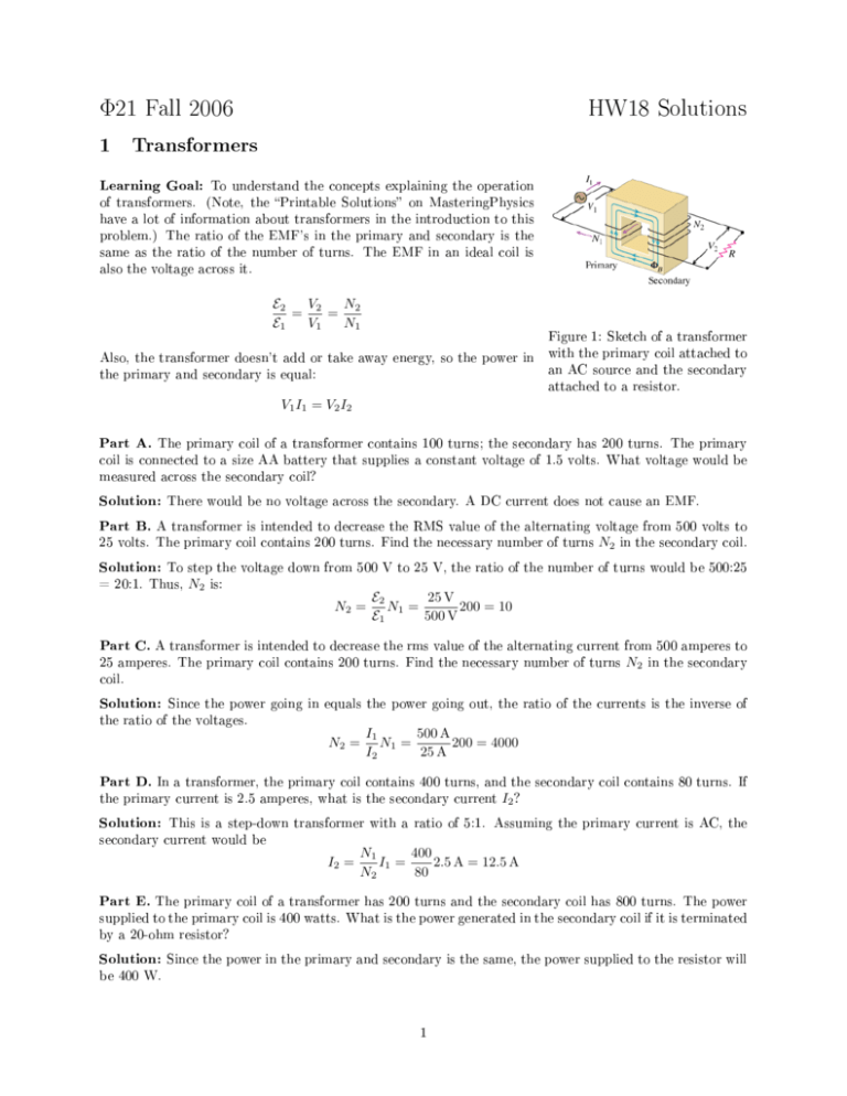
Φ21 Fall 2006 1 HW18 Solutions Transformers Learning Goal: To understand the concepts explaining the operation of transformers. (Note, the Printable Solutions on MasteringPhysics have a lot of information about transformers in the introduction to this problem.) The ratio of the EMF's in the primary and secondary is the same as the ratio of the number of turns. The EMF in an ideal coil is also the voltage across it. E2 V2 N2 = = E1 V1 N1 Figure 1: Sketch of a transformer Also, the transformer doesn't add or take away energy, so the power in the primary and secondary is equal: with the primary coil attached to an AC source and the secondary attached to a resistor. V1 I1 = V2 I2 Part A. The primary coil of a transformer contains 100 turns; the secondary has 200 turns. The primary coil is connected to a size AA battery that supplies a constant voltage of 1.5 volts. What voltage would be measured across the secondary coil? Solution: There would be no voltage across the secondary. A DC current does not cause an EMF. Part B. A transformer is intended to decrease the RMS value of the alternating voltage from 500 volts to 25 volts. The primary coil contains 200 turns. Find the necessary number of turns N2 in the secondary coil. Solution: To step the voltage down from 500 V to 25 V, the ratio of the number of turns would be 500:25 = 20:1. Thus, N2 is: N2 = E2 25 V N1 = 200 = 10 E1 500 V Part C. A transformer is intended to decrease the rms value of the alternating current from 500 amperes to 25 amperes. The primary coil contains 200 turns. Find the necessary number of turns N2 in the secondary coil. Solution: Since the power going in equals the power going out, the ratio of the currents is the inverse of the ratio of the voltages. N2 = I1 500 A N1 = 200 = 4000 I2 25 A Part D. In a transformer, the primary coil contains 400 turns, and the secondary coil contains 80 turns. If the primary current is 2.5 amperes, what is the secondary current I2 ? Solution: This is a step-down transformer with a ratio of 5:1. Assuming the primary current is AC, the secondary current would be I2 = 400 N1 I1 = 2.5 A = 12.5 A N2 80 Part E. The primary coil of a transformer has 200 turns and the secondary coil has 800 turns. The power supplied to the primary coil is 400 watts. What is the power generated in the secondary coil if it is terminated by a 20-ohm resistor? Solution: Since the power in the primary and secondary is the same, the power supplied to the resistor will be 400 W. 1 Part F. The primary coil of a transformer has 200 turns, and the secondary coil has 800 turns. transformer is connected to a 120-volt (rms) ac source. What is the (rms) current I1 The in the primary coil if the secondary coil is terminated by a 20-ohm resistor? Solution: The RMS voltage in the secondary will beV2 With the 20 Ω = (N2 /N1 ) V1 = (800/200) · 120 = 480 V resistor, the current in the secondary will be I2 = V2 /R = (480 V) / (20 Ω) = 24 A. In order to produce this secondary current, the primary current would have to be larger I1 = N2 800 I2 = 24 A = 96 A N1 200 Part G. A transformer supplies 60 watts of power to a device that is rated at 20 volts (rms). The device is connected to the secondary coil. The primary coil is connected to a 120-volt (rms) ac source. What is the current I1 in the primary coil? Solution: The power is the same on both sides of the transformer, so the current is I1 = P 60 W = = 0.5 A V1 120 V Part H. The voltage and the current in the primary coil of a nonideal transformer are 120 V and 2.0 A. The voltage and the current in the secondary coil are 19.4 V and 11.8 A. What is the eciency e of the transformer? The eciency of a transformer is dened as the ratio of the output power to the input power, expressed as a percentage: e = 100 % (Pout /Pin ). Solution: The eciency is e = 100 % 2 (19.4 V) (11.8 A) = 95.4 % (120 V) (2.0 A) Problem K34.19 A square parallel-plate capacitor 5.30 cm on a side has a 0.540 mm gap. What is the displacement current in the capacitor if the potential dierence across the capacitor is increasing at 500,000 V/s? (Displacement current is dened on page 1100 of the book. It is part of the extra term in Ampere's Law.) ∫ E ~ · dA ~ is the electric ux. Just ID = ²0 dΦ E dt , where ΦE = 2 dE like magnetic ux, usually ΦE = EA. Taking the time derivative, ID = ²0 A dt . The area is A = (0.0530 m) and the electric eld and voltage in the capacitor are related by V = Ed, so Solution: The displacement current is dened as 2 ID = ²0 3 A dV (0.0530 m) = ²0 (500, 000 V/s) = 2.30 × 10⁻⁵ A d dt (0.000540 m) Problem K35.23 What capacitor in series with a 100 Ω resistor and a 23.0 mH inductor will give a resonance frequency of 1010 Hz? Solution: The resonant frequency depends only on the inductor and the capacitor. 2 ω 2 = (2πf ) = 1 LC ⇒ C= 1 2 (2πf ) L = 2 1 2 (2π1010 Hz) (23 × 10−3 H) = 1.08 × 10⁻⁶ F 4 Problem K35.48 A series RLC circuit consists of a 100 Ω resistor, a 0.10 H inductor, and a 100 µF capacitor. It is attached to a 120 V/60 Hz power line. Part A. What is the peak current I0 ? Solution: The loop equation for a series RLC circuit is E(t) − I(t)R − L dI 1 − Q(t) = 0 dt C Q(t) = Where the charge on the capacitor is constant set so the average Q ∫ I(t) dt with the arbitrary is zero. The current as a function of time is I(t) = I0 cos ωt + φ Because of the sin's and cos's, to nd I0 , we draw the phasor diagram. The lengths of the vectors are VR VL VC E0 = VT = I0 R = I0 XL = I0 ωL I0 = I0 XC = ωC √ I0 , XL = ωL = 2π (60 Hz) (0.1 H) = 37.7 Ω √ 2VRMS , we get noting that E0 = E0 E0 I0 = √ = √ ( 2 R2 + (XL − XC ) R2 + ωL − Part B. What is the phase angle φ RLC circuit. 2 VR2 + (VL − VC ) = The reactances are By solving for Figure 2: Phasor diagram for an and XC = 1 ωC = 1 2π(60 Hz)(100×10−6 F) = 26.5 Ω. √ 2 120 V √ = = 1.69 A ) 2 2 2 1 (100 Ω) + (37.7 Ω − 26.5 Ω) ωC in degrees? Solution: The phase angle is the angle between the total voltage VT and the total current I0 in the phasor diagram. By inspection, it has the value φ = tan−1 ( VL − VC VR ) = tan−1 ( XL − XC R ) = tan−1 ( 37.7 Ω − 26.5 Ω 100 Ω ) = 0.111 radians = 6.39◦ Part C. What is the avergae power loss? Solution: The only component with a power loss is the resistor. The instantaneous power is the average power is 2 2 Pave = IRMS VRMS = (IRMS ) R = (1.69 A) (100 Ω) I02 R = = 142 W 2 2 3 P = IV , and
