A REALTIME, MEMORY EFFICIENT FINGERPRINT
advertisement
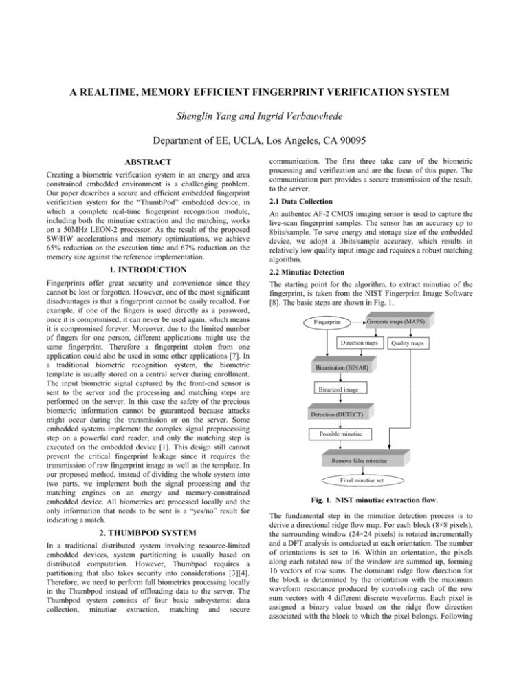
A REALTIME, MEMORY EFFICIENT FINGERPRINT VERIFICATION SYSTEM Shenglin Yang and Ingrid Verbauwhede Department of EE, UCLA, Los Angeles, CA 90095 ABSTRACT Creating a biometric verification system in an energy and area constrained embedded environment is a challenging problem. Our paper describes a secure and efficient embedded fingerprint verification system for the “ThumbPod” embedded device, in which a complete real-time fingerprint recognition module, including both the minutiae extraction and the matching, works on a 50MHz LEON-2 processor. As the result of the proposed SW/HW accelerations and memory optimizations, we achieve 65% reduction on the execution time and 67% reduction on the memory size against the reference implementation. 1. INTRODUCTION Fingerprints offer great security and convenience since they cannot be lost or forgotten. However, one of the most significant disadvantages is that a fingerprint cannot be easily recalled. For example, if one of the fingers is used directly as a password, once it is compromised, it can never be used again, which means it is compromised forever. Moreover, due to the limited number of fingers for one person, different applications might use the same fingerprint. Therefore a fingerprint stolen from one application could also be used in some other applications [7]. In a traditional biometric recognition system, the biometric template is usually stored on a central server during enrollment. The input biometric signal captured by the front-end sensor is sent to the server and the processing and matching steps are performed on the server. In this case the safety of the precious biometric information cannot be guaranteed because attacks might occur during the transmission or on the server. Some embedded systems implement the complex signal preprocessing step on a powerful card reader, and only the matching step is executed on the embedded device [1]. This design still cannot prevent the critical fingerprint leakage since it requires the transmission of raw fingerprint image as well as the template. In our proposed method, instead of dividing the whole system into two parts, we implement both the signal processing and the matching engines on an energy and memory-constrained embedded device. All biometrics are processed locally and the only information that needs to be sent is a “yes/no” result for indicating a match. 2. THUMBPOD SYSTEM In a traditional distributed system involving resource-limited embedded devices, system partitioning is usually based on distributed computation. However, Thumbpod requires a partitioning that also takes security into considerations [3][4]. Therefore, we need to perform full biometrics processing locally in the Thumbpod instead of offloading data to the server. The Thumbpod system consists of four basic subsystems: data collection, minutiae extraction, matching and secure communication. The first three take care of the biometric processing and verification and are the focus of this paper. The communication part provides a secure transmission of the result, to the server. 2.1 Data Collection An authentec AF-2 CMOS imaging sensor is used to capture the live-scan fingerprint samples. The sensor has an accuracy up to 8bits/sample. To save energy and storage size of the embedded device, we adopt a 3bits/sample accuracy, which results in relatively low quality input image and requires a robust matching algorithm. 2.2 Minutiae Detection The starting point for the algorithm, to extract minutiae of the fingerprint, is taken from the NIST Fingerprint Image Software [8]. The basic steps are shown in Fig. 1. Generate maps (MAPS) Fingerprint Direction maps Quality maps Binarization (BINAR) Binarized image Detection (DETECT) Possible minutiae Remove false minutiae Final minutiae set Fig. 1. NIST minutiae extraction flow. The fundamental step in the minutiae detection process is to derive a directional ridge flow map. For each block (8×8 pixels), the surrounding window (24×24 pixels) is rotated incrementally and a DFT analysis is conducted at each orientation. The number of orientations is set to 16. Within an orientation, the pixels along each rotated row of the window are summed up, forming 16 vectors of row sums. The dominant ridge flow direction for the block is determined by the orientation with the maximum waveform resonance produced by convolving each of the row sum vectors with 4 different discrete waveforms. Each pixel is assigned a binary value based on the ridge flow direction associated with the block to which the pixel belongs. Following the binarization, the detection step methodically scans the binary image of a fingerprint, identifying localized pixel patterns that indicate the ending or bifurcation of a ridge. All minutiae candidates are pointed out by performing these steps. The final step is to remove false minutiae from the candidates and keep the true ones. to the repetitive DFT calculation in creating the direction map. Based on the profiling result, optimization should be considered for the calculations in MAPS of the minutiae detection. OTHERS 3% Store 4% BINAR 11 % 2.3 Matching DETECT 12% The matching step compares the likeness of one fingerprint image to the template. It uses the minutiae of the previous step to perform this comparison. The algorithm flow is shown in Fig. 2. Others 8% Logical 9% Mult 41% Branch 8% MAPS 74% Load 15% Add 15% Find reference points in two minutiae sets (a) Fig. 3. (a) Profiling of the execution time for the minutiae; (b) Instruction-level profiling of MAPS Align other minutiae Compute matching score Fig. 2. Matching flow. The first step is to find out the correspondence of these two minutiae sets by comparing the local structures. Then the other minutiae are aligned by converting them to a polar coordinate system based on the corresponding pair. Based on the transformed minutiae sets, similarity evaluation is performed and the matching score is calculated out. 2.4 System Analysis and Testing Using the algorithm described above we can perform fingerprint verification on ThumbPod. The sensor used for scanning has a relatively small area (13×13mm2), so the performance is strongly dependent on which part of the finger is captured by the sensor. To eliminate this problem we use a two-template system in ThumbPod. The system is tested with live-scan fingerprints. The image set consists of 10 fingerprints per finger from 10 different fingers for total 100 fingerprints images. Each fingerprint is compared with every two other fingerprints and the two match scores are ported into a decision engine in order to get the final matching result. So totally 7,200 decisions are reached for the matched case and 81,000 decisions for mismatched case. We have achieved 0.5% FRR and 0.01% FAR. 3. OPTIMIZATION FOR SPEED Implementing the fingerprint recognition system on ThumbPod requires not only accuracy, but also high speed performance. The TSIM SPARC simulator is used for profiling [2]. Simulations show that the minutiae extraction takes most (~99%) of the execution time. Therefore, we focus on software and hardware optimizations for the minutiae extraction module [9]. 3.1 Profiling of the Minutiae Detection Fig.3(a) shows the profiling result of the minutiae detection. The execution time of BINAR and DETECT are 11% and 12% of the total, respectively. They are not considered as a system bottleneck; on the contrary, MAPS occupies 74% of the total execution time. Therefore, the detailed algorithm is checked to speedup the MAPS at the instruction level. Fig. 3(b) shows the instruction-level profiling of MAPS. The instructions of multiply (Mult) and addition (add) sum up to 56% of the total MAPS due (b) 3.2 Software Optimization Considering that the ridges in a fingerprint are usually continuous, the neighboring blocks tend to have similar directions. Taking advantage of this characteristic, the number of DFT calculations can be reduced significantly. An example of direction map is shown in Fig. 4. -1 -1 -1 -1 -1 -1 -1 -1 -1 -1 -1 -1 -1 -1 -1 -1 -1 -1 -1 -1 -1 -1 -1 -1 -1 -1 -1 -1 -1 -1 -1 -1 -1 5 5 5 5 4 4 3 3 3 3 3 2 2 2 3 2 1 0 0 15 15 15 15 14 14 14 14 9 9 12 -1 -1 5 4 5 5 5 3 3 3 3 3 3 2 2 2 1 1 1 0 0 15 15 15 14 14 15 13 11 13 12 12 -1 -1 5 5 6 6 6 3 3 3 3 3 2 2 2 2 1 1 1 0 0 15 15 14 14 13 15 14 13 13 12 12 -1 -1 6 5 5 5 5 4 4 3 3 3 3 2 2 2 1 2 1 0 0 15 14 13 14 7 7 13 13 12 12 12 -1 -1 5 5 5 5 5 5 4 4 3 3 3 3 2 2 0 1 1 1 0 0 14 14 13 11 13 13 13 12 12 12 -1 -1 6 6 5 5 5 5 4 4 3 3 3 2 2 2 0 1 1 1 0 15 15 15 14 14 13 13 13 12 12 12 -1 -1 7 7 6 5 5 5 5 4 4 3 3 3 2 2 1 1 1 1 0 15 15 14 14 14 14 14 12 12 11 12 -1 -1 7 7 6 6 5 5 5 5 5 4 4 3 3 2 2 1 1 1 0 0 14 14 15 14 14 14 13 13 12 12 -1 -1 7 7 7 6 6 6 5 5 5 5 4 3 3 2 2 2 1 1 0 0 0 14 15 14 14 13 13 13 12 12 -1 -1 7 7 7 7 6 6 6 6 5 5 5 4 3 2 2 0 1 1 0 0 0 15 15 14 14 13 13 13 13 12 -1 -1 8 7 7 7 6 6 6 6 5 6 5 3 3 3 2 1 1 0 0 0 0 15 15 14 13 13 12 14 13 13 -1 -1 8 7 7 7 7 7 6 6 6 5 6 3 3 3 2 1 1 0 0 0 15 15 14 14 13 13 13 13 13 12 -1 -1 8 6 7 7 7 7 7 7 7 6 6 5 4 4 3 2 1 0 0 0 15 14 14 14 13 13 13 12 12 12 -1 -1 8 7 7 8 8 8 8 7 7 7 7 8 7 7 7 7 8 11 6 0 15 14 14 13 13 13 12 12 12 12 -1 -1 8 8 8 8 8 8 9 9 8 8 8 9 8 8 8 8 8 11 11 14 14 14 13 13 13 12 12 12 11 11 -1 -1 9 9 8 8 8 9 9 9 10 10 9 10 9 10 10 10 13 13 13 13 13 13 13 13 12 12 12 12 11 11 -1 -1 9 9 9 9 9 9 10 10 10 10 11 11 11 11 11 11 12 13 13 13 13 13 13 13 12 12 12 12 11 11 -1 -1 9 9 9 9 9 10 10 10 11 11 11 11 11 12 12 12 13 13 13 13 13 13 13 12 12 12 12 12 11 11 -1 -1 8 9 9 9 10 10 10 11 11 11 11 11 12 12 12 12 13 13 13 13 13 13 12 12 12 11 11 12 11 11 -1 -1 10 9 9 10 10 10 11 11 11 11 11 12 12 12 12 13 13 13 13 12 13 13 13 12 12 12 12 11 11 11 -1 -1 10 11 11 11 11 11 11 11 11 11 12 12 12 12 13 13 13 13 13 13 13 13 12 12 12 12 12 12 12 11 -1 -1 11 12 11 11 12 12 12 11 11 10 13 13 13 13 13 13 13 12 13 13 13 13 12 13 12 12 12 12 12 11 -1 -1 10 12 11 12 12 12 12 11 10 11 12 12 12 12 13 13 13 12 12 13 13 13 12 13 12 12 11 11 11 10 -1 -1 11 11 11 11 12 12 12 12 11 12 13 13 13 12 13 13 13 13 12 13 13 12 13 13 12 12 12 11 11 10 -1 -1 11 11 11 11 12 12 12 12 12 13 13 13 13 12 13 13 14 14 13 13 13 13 13 12 12 12 12 11 10 10 -1 -1 11 11 11 12 12 12 13 13 13 13 13 13 13 14 11 13 14 14 13 13 13 13 12 12 12 12 12 13 10 10 -1 -1 11 11 11 12 12 12 13 13 13 13 13 14 14 13 11 12 13 13 13 13 13 12 13 12 12 12 12 12 11 9 -1 -1 11 12 12 12 12 12 13 13 13 13 13 13 14 13 12 12 13 13 13 13 13 13 12 12 12 11 12 12 11 10 -1 -1 12 12 12 12 13 13 13 13 13 13 13 13 14 14 13 12 13 13 13 13 13 12 12 12 11 12 12 11 11 11 -1 -1 12 12 12 13 13 13 13 13 13 13 13 13 13 13 12 13 14 13 13 13 13 12 12 12 12 12 12 11 11 12 -1 -1 -1 -1 -1 -1 -1 -1 -1 -1 -1 -1 -1 -1 -1 -1 -1 -1 -1 -1 -1 -1 -1 -1 -1 -1 -1 -1 -1 -1 -1 -1 -1 Fig. 4. Example of Direction Map. “-1” is no-direction because zero-padding in the image. The first direction data θ =5 is calculated with the same method as the original program. When deciding the direction of the following data, the DFTs for θ =4,5,6 are calculated first, because the result is most likely to be close. If the total energy for θ =5 is greater than both its neighbors ( θ =4,6) and a threshold value ETH , the direction data of θ =5 is considered as the result. Otherwise, θ is incremented or decremented until the total energy for θ has a peak with a value larger than ETH . The execution speed as well as the matching error rate is measured when changing ETH from 10M to 35M. The error rate is within an acceptable range when ETH is larger than 20M. In this paper, we choose the value of 27M. 3.3 DFT Accelerator of the Minutiae Detection The software optimization reduces the number of DFT and results in a significant speedup for the minutiae detection. However, there are still a large number of DFT calculations for a 256×256 pixels image when setting the ETH to a proper value. Therefore, DFT hardware acceleration is needed in addition to the software optimization. AMBA Peripheral Bus Data Address Control Signal DFT Accelerator Memory Mapped I/F heap bottom and the stack pointer dynamically during the program running time. Taking program size into consideration, a dynamic memory usage trace map is generated. From this trace map, we can get information about the overall memory requirement as well as the memory bottleneck of the application. In the following subsections, the memory usage analysis is carried out using this NIST software as the starting point. In addition, memory optimizations oriented by the analysis results are described. 4.2 Baseline Result for the Minutiae Detection Controller DFT (k = 1) DFT (k = 2) DFT (k = 3) DFT (k = 4) 32bit Data Bus Implementing the methodology described in section 4.1 to the baseline program, the memory trace map is shown in Fig. 6(a), in which the peak memory usage of the system is 1,572Kbytes, including 325Kbytes of program segment memory and 1,247Kbytes of data segment memory. 4.3 Memory Optimization Fig. 5. Block diagram for the memorymapped DFT accelerator The final version of the accelerator only implements MAC computations for sine and cosine part separately [Fig.5]. In the multiply operation, Canonic Signed Digit (CSD) is used for saving hardware resources. The energy calculation part is not included because it needs square operation of 16 bits data, which requires a general multiplier. As a result of these optimizations, the execution time of the minutia detection is reduced to about 4 seconds. 4. MEMORY OPTIMIZATION As new processors continuously improve the performance of embedded systems, the processor-memory gap widens and memory presents a major bottleneck in both storage area and energy consumption. As mentioned before, in the ThumbPod system the major computational bottleneck is the fingerprint minutiae detection algorithm. Like many other image processing algorithm, it is array-dominated. Therefore, apart from optimizations for high-speed calculation, memory management is also necessary. In this section, we will introduce a memory analysis method, and several optimization techniques are implemented based on the analysis result. 4.1 Memory Analysis Methodology When a program is running, the memory module is divided into two parts: program segment and data segment, which includes a heap and a stack. The heap starts from the bottom of the program segment and increases when the latest reserved block is beyond its range. Whenever there is dynamic memory allocation, a block of memory is reserved for later use. When a memory free happens, the specific memory block is returned to the memory pool. On the other hand, the stack pointer position changes when a function call is executed or returned. Generally, the stack and the heap grow and shrink in opposite direction. A collision of stack and heap implies a fatal error state. At any particular moment, the memory usage of the system is determined by the sum of the size of program, heap and stack as shown in Equation 1: (1) M Total = M program + M Heap + M stack By inserting the memory trace agents in the program where memory usage changes can happen, we get the position of the For most embedded systems, memory size beyond 1Mbytes is too expensive. In order to reduce the memory requirement for this application, we try to shrink the program size as well as the running time memory usage based on the information obtained from the memory trace map. 4.3.1 Architecture Optimization The NIST starting point program is floating-point based, while the LEON-2 processor only supports fixed-point computation. Therefore, we perform a fixed-point refinement optimization by replacing all the floating computation with 32bit long integer ones. From the memory trace map (Fig. 6(b)) of the fixed-point refined program, we notice that both the program segment size and the data segment size decrease. This is because, on the one hand, fixed-point refinements remove many floating-point calculation related libraries; on the other hand, the size of the elements of some arrays are modified from 8bytes “double” type to 4bytes “int” type, which reduces the storage memory by half. In total, the memory requirement for fixed-refined program is 1267Kbytes. 4.3.2 “In-place” Optimization The memory trace map Fig.6(a) and (b) show that there is a major jump, which introduces most of the memory usage in a very short period. Our idea for reducing the data segment memory is first finding out where the jump happens, then studying the algorithm to figure out the reason for the big memory use and implementing memory management techniques to remove or lower the jump. Detailed investigation of the minutiae detection algorithm of the ThumbPod embedded system shows that the biggest jump happens when a routine named “pixelize_map” is called. The functionality of this routine is to convert the block-based maps for direction, low flow flag, and high curve flag into pixel-based ones. For each pixelized map, 262,144 (256×256×4) bytes of memory are required since for each pixel, one 32-bits integer is used to present each value. This results in the bottleneck jump in the memory trace map. The dimensions for the three maps are exactly the same. Moreover, the values in direction_map vary from 0 to 32 and low_flow_map and high_curve_map consist of only 0 and 1. Therefore taking one corresponding element from each map, only 6 bits are required per pixel (four bits for direction_map, one for low_flow_map, and one for high_curve_map). It is 10,000 Execution Time [msec] possible to compress these three different maps into one since we can combine three elements (one from each map) in one 32bit integer. By doing this, the peak memory requirement becomes 744Kbytes (Fig. 6(c)). The data segment memory decreases by 590Kbytes compared to the previous result, while the program segment size increases by 47Kbytes. The reason for program size increasing is that additional calculations are needed for the compression and decompression of the pixelized maps. M Bytes 5,000 4,000 3,000 2,000 1,000 Memory Usage Memory usage ORG. S/W OPT. +HW_Acc. (Fixed-point) ETH= 27M 0.8 0.4 2 4 6 (a) 8 (Kbytes) 1200 1000 800 600 400 200 0 1 2 3 4 (b) 5 (×105) 0.5 0.4 Memory usage M Bytes 0.4 0.2 0.3 0.2 0.1 1 2 (c) 3 4 5 (×105) fixed-point text segment op-1 data segment op-2 7. REFERENCES 0.4 M Bytes 0.6 ETH= 10M (b) Fig. 7. (a) Execution time reduction; (b) Memory reduction. 0.8 12 10 (×105) M Bytes SW_OPT. +HW_Acc. (a) baseline 1.2 Memory usage BINAR 6,000 0 M Bytes 1.2 0 DETECT 7,000 0 As shown in Fig. 6(c), the memory requirement bottleneck is still in the pixelize_map routine. Further optimization can be implemented by eliminating this routine. Instead of generating whole pixelized maps, we calculate the map value for each pixel only when it is referred in the program. This technique removes the big memory usage jump in the memory trace map. The drawback of it is that the pixel index needs to be calculated each time it is referred. The result of this method is shown as Fig. 6(d). Comparison of the results shows that both the program segment size and the data segment size decrease. The total memory requirement is 483K Bytes. 0 MAPS 8,000 4.3.3 On-line Calculation 1.6 OTHERS 9,000 0 1 2 3 (d) 4 5 (×105) Fig. 6. Memory trace maps for: (a) baseline; (b) fixed-point refined; (c) “in-place” optimized; (d) final optimized. 5. CONCLUSION In this paper, we design an efficient embedded fingerprint recognition system. Both high-speed optimization and memory optimization are implemented. Fig. 7 shows the overall optimization results. Fig. 7(a) presents the execution time reduction of the minutia detection. Fig. 7(b) shows the memory reduction. 6. ACKNOWLEDGEMENTS The authors would like to acknowledge the funding of NSF account no CCR-0098361, the Langlois foundation and the ThumbPod teammates. [1] Gil, Y., Moon, D., Pan, S. and Chung, Y., Fingerprint Verification System Involving Smart Card, Information Security and Cryptology - ICISC 2002 (LNCS 2587), Nov. 2002, Seoul, Korea. [2] http://www.gaisler.com [3] http://www.ThumbPod.com [4] Hwang, D., Schaumont, P., Fan, Y., Hodjat, A., Lai, B., Sakiyama, K., Yang, S. and Verbauwhede, I., Design flow for HW/SW acceleration transparency in the ThumbPod secure embedded system, Proceedings of 40th ACM/IEEE Design Automation Conference, Anaheim, CA, pp.60-65, June 2003. [5] Jiang, X. and Yau, W.-Y., Fingerprint minutiae matching based on the local and global structures, Proceedings of International Conference on Pattern Recognition, pp.60386041, September 2000. [6] Panda, P., Catthoor, F., Dutt, N., Danckaert, K., Brockmeyer, E., Kulkarni, C., Vandercappelle, A. and Kjeldsberg, P.G., Data and memory optimization techniques for embedded systems, ACM Transactions on Design Automation of Electronic systems, vol.6, no.2, pp.149-206, April 2001. [7] Prabhakar, S., Pankanti, S., and Jain, A. K., Biometric Recognition: Security and Privacy Concerns, IEEE Security and Privacy Magazine, Vol. 1, No. 2, pp. 33-42, MarchApril 2003. [8] User’s Guide to NIST Fingerprint Image Software (NFIS). NISTIR 6813, National Institute of Standards and Technology. [9] Yang, S., Sakiyama, K. and Verbauwhede, I., A Secure and Efficient Fingerprint Verification System for Embedded Systems, 37th Asilomar Conference on Signal, Systems, and Computers, Nov. 2003, Pacific Grove, CA.
