Measurement of magnetic fields

The measurement of magnetic fields
The flux density of magnetic fields may be measured by various methods, three of which are described below. The first and third methods are only suitable for constant magnetic fields while the second may be used for either steady or varying fields.
(a) The Hall probe
This is simply a slice of semiconducting material with a small current passing through it. When it is placed in the magnetic field a p.d. that is directly proportional to the magnetic flux density is produced across the slice at right angles to the current direction.
The instrument must first be calibrated by placing it in a magnetic field of known flux density, such as the centre of a long solenoid. The sensitivity of the probe in millivolts per tesla can then be found. The probe is then placed in the unknown field and its flux density found.
(See: 16-19/Electronics/Semiconductors/Text/Hall effect)
(b) The search coil
This method can be used to measure both constant and varying fields and we will consider first its use for varying fields.
(i) Measuring varying magnetic fields
The search coil is a small flat coil of fine insulated wire with a large number of turns. Those in use in schools usually have between 500 and 2000 turns with an average diameter of 0.5
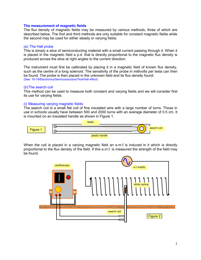
cm. It is mounted on an insulated handle as shown in Figure 1. leads search coil
Figure 1 plastic handle
When the coil is placed in a varying magnetic field an e.m.f is induced in it which is directly proportional to the flux density of the field. If this e.m.f. is measured the strength of the field may be found. oscilloscope a.c supply slinky spring search coil
Figure 2
1
The search coil is connected to an oscilloscope and calibrated in a known field. The induced e.m.f. is displayed most conveniently as a vertical line, the time base of the oscilloscope being switched off (Figure 2). The bigger the line the larger the flux density of the field. The coil is then placed in the unknown field and the value of this field found.
(ii) Measuring steady magnetic fields
In the measurement of steady magnetic fields the search coil is connected to a ballistic galvanometer ( a sensitive meter where the maximum deflection is proportional to the charge flowing in a short time).
The search coil is placed in the field and held still, the galvanometer reading will be zero. If the coil is now removed quickly to a large distance from the field a current will flow in the coil and it can be shown that
Search coil the maximum deflection shown by the galvanometer is proportional to the field strength. (Figure 3)
(c) The Earth inductor
This instrument, as its name suggests, is used primarily for the measurement of the flux density of
Figure 3 the magnetic field of the Earth. The principle is the same as that described for the search coil, but since the flux density of the Earth's field is low a coil of many turns and large area is needed because the induced voltages will be small.
The coil is placed in the position shown in Figure 4(a) and rotated suddenly through 180 o ; the resulting kick on the galvanometer is proportional to the charge passed which is proportional to the flux cut. Therefore if the experiment is repeated starting with the coil in position shown in
Figure 4(b) the ratio of the two deflections gives the ratio of the vertical and horizontal components of the Earth's field, that is, the tangent of the angle of dip.
N
B v
W
W N
S B
H
E
S
E
Figure 4(a) Figure 4(b)
2


