Installation Guide for the Micronet CE-507
advertisement
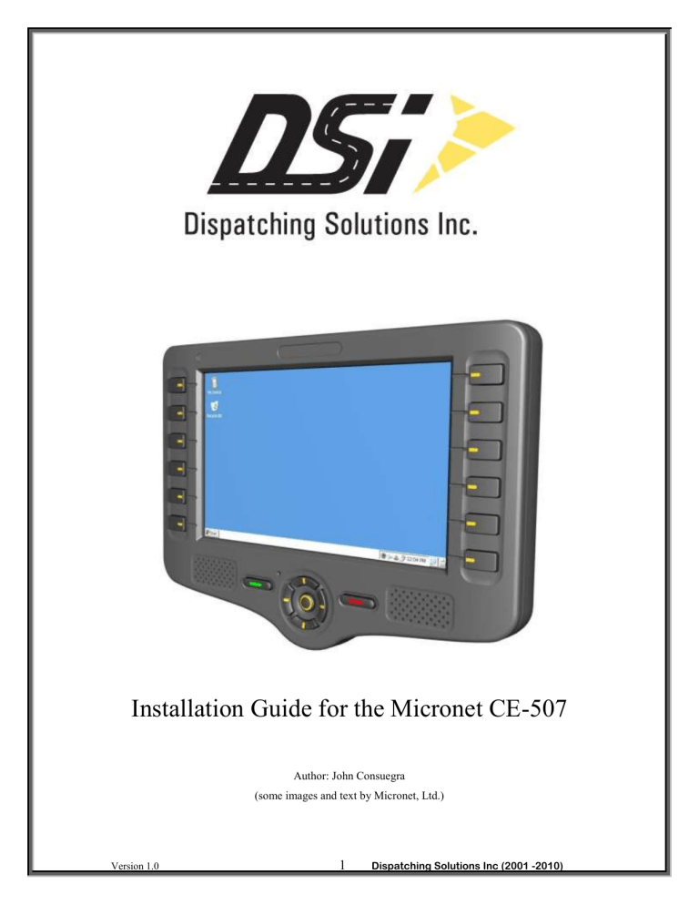
Installation Guide for the Micronet CE-507 Author: John Consuegra (some images and text by Micronet, Ltd.) Version 1.0 1 Dispatching Solutions Inc (2001 -2010) This is a general installation guide for the components of the Micronet CE-507 MDT wireless device. This manual serves as a guideline of the installation procedures for a three axle tractor. The guide will walk you through the step by step process on an installation that was done on a 2004 three axle Sterling Tractor. Pictures are provided along with the steps that were taken to install the device. A detailed explanation of each component accompanies each step. This guide serves as a template to install this device and can vary from vehicle to vehicle. Components Needed The Micronet CE-507 Version 1.0 2 Dispatching Solutions Inc (2001 -2010) Power Converter with 3-Amp Fuse Main Interface Cable Version 1.0 3 Dispatching Solutions Inc (2001 -2010) Communications Antenna GPS Antenna Version 1.0 4 Dispatching Solutions Inc (2001 -2010) Mounting Arm and Screws NOTE: You will also need a 5/64 Allen Wrench (Not Included) in order to secure the Main Interface Cable to the CE-507. Version 1.0 5 Dispatching Solutions Inc (2001 -2010) Installation – Connecting Power and Main Interface Cable Locate the fuse terminal in your vehicle and find a live, always-on power source that the power cable can be connected to. In most vehicles a general power source is extracted from the lighter connectors. Locate the battery power source and a ground in your vehicle and use that as a power source for the Micronet CE-507 wireless device. Version 1.0 6 Dispatching Solutions Inc (2001 -2010) Connect the red wire coming from the fuse to the always-on power source. Connect the ground (black wire) to the ground source. For example: Secure the Power Converter somewhere under or behind the dash so that it doesn’t bounce around when vehicle is in motion. We recommend using zip-ties for this. Version 1.0 7 Dispatching Solutions Inc (2001 -2010) Main Interface Cable The Main interface cable must be attached to the “Con1” terminal connector of the device. This cable is provided with an integrated power adaptor box. This box converts the vehicle 12V or 24V power signal to 5V, as required by the device. Version 1.0 8 Dispatching Solutions Inc (2001 -2010) Antenna Connections Both GPS and Communication antennas should be place on top of the dash on the passenger side, as close to the front windshield as possible. They should be placed sideby-side, not one on top of the other. If necessary, you can use Velcro or double-sided tape to secure the GPS antenna. Snake the antenna cables down through the dash and out to the CE-507. Connect each antenna to the appropriate connector on the device. GPS Antenna Communications Antenna NOTE: Any excess antenna and interface cable length should be coiled neatly somewhere under the dash. We recommend using zip-ties for this. Version 1.0 9 Dispatching Solutions Inc (2001 -2010) Mounting Arm – Use the short screws to attach mount to back of CE device. The round base of the mount should be attached to an appropriate location on the console, dash or floor. Once installation is complete, make note of the IMEI number of the device and the vehicle ID that it was installed in. Version 1.0 10 Dispatching Solutions Inc (2001 -2010) If you have any questions or need assistance, please do not hesitate to contact the DSI Support Team. DSI Support Team contact: Phone: 909.460.6404 Email: support@dispatchingsolutions.com Version 1.0 11 Dispatching Solutions Inc (2001 -2010)


