chapter 11 - Extras Springer
advertisement
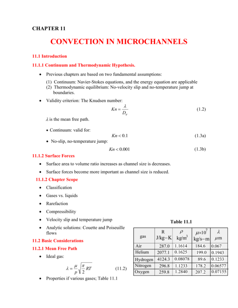
CHAPTER 11 CONVECTION IN MICROCHANNELS 11.1 Introduction 11.1.1 Continuum and Thermodynamic Hypothesis. Previous chapters are based on two fundamental assumptions: (1) Continuum: Navier-Stokes equations, and the energy equation are applicable (2) Thermodynamic equilibrium: No-velocity slip and no-temperature jump at boundaries. Validity criterion: The Knudsen number: Kn is the mean free path. Continuum: valid for: No-slip, no-temperature jump: (1.2) De Kn 0.1 (1.3a) Kn 0.001 (1.3b) 11.1.2 Surface Forces Surface area to volume ratio increases as channel size is decreases. Surface forces become more important as channel size is reduced. 11.1.2 Chapter Scope Classification Gases vs. liquids Rarefaction Compressibility Velocity slip and temperature jump Analytic solutions: Couette and Poiseuille flows Table 11.1 gas 11.2 Basic Considerations Air Helium 11.2.1 Mean Free Path Ideal gas: RT (11.2) p 2 Properties if various gases; Table 11.1 J/kg K kg/m3 R 287.0 2077.1 Hydrogen 4124.3 Nitrogen 296.8 Oxygen 259.8 kg/s m m 107 1.1614 0.1625 184.6 199.0 0.08078 89.6 178.2 207.2 1.1233 1.2840 0.067 0.1943 0.1233 0.06577 0.07155 2 11.2.2 Why Microchannels? The heat transfer coefficient increases as channel size is decreased. Examine fully developed flow through tubes and note the effect of diameter h 3.657 k D (11.3) 11.2.3 Classification. Based on Knudsen number Kn 0.001 continuum, no slip flow 0.001 Kn 0.1 continuum, slip flow 0.1 Kn 10 transition flow 10 Kn free molecular flow (11.4) 11.2.4 Macro and Microchannels Macrochannels Continuum and thermodynamic equilibrium model applies. No-velocity slip and no-temperature jump. Microchannels Failure of macrochannel theory and correlation. Distinguishing factors: two and three dimensional effects, axial conduction, dissipation, temperature dependent properties, velocity slip and temperature jump at the boundaries and the increasing dominant role of surface forces. 11.2.5 Gases vs. Liquids Mean free paths of liquids are much smaller than those of gases. Onset of failure of thermodynamic equilibrium and continuum is not well defined for liquids. Surface forces for liquids become more important. Liquids are almost incompressible while gases are compressible. 11.3 General Features Rarefaction: Knudsen number effect. Compressibility: large channel pressure drop, changes in density (compressibility). Dissipation: Increased viscous effects. 11.3.1 Flow Rate No-velocity slip: Fig. 11.3a Velocity slip: Fig. 11.3b Flow rate Q : Macrochannel theory underestimates flow rate: (a) (b) Fig. 11.3 3 Qe 1 Qt (11.5) 11.3.2 Friction Factor Friction coefficient C f w Cf (1 / 2) u m2 Friction factor f f 1 D p 2 L um2 (11.6) Fully developed laminar flow in macrochannels: f Re Po (4.37a) (11.7) Po is known as the Poiseuille number Macrochannel theory does not predict Po. The following ratio is a measure of prediction error Poe Pot C* (11.8) Po appears to depend on the Reynolds number. Both increase and a decrease in C are reported. 11.3.3 Transition to Turbulent flow Macrochannels Re t uD 2300 (6.1) Microchannels: reported transition Reynolds numbers ranged from 300 to 16,000 11.3.4 Nusselt number Macrochannels: Fully developed laminar flow: constant Nusselt number, independent of Reynolds number. Microchannels: Macrochannel theory does not predict Nu. The following ratio is a measure of reported departure from macrochannel prediction 0.21 ( Nu) e 100 ( Nu) t (11.9) 11.4 Governing Equations In the slip-flow domain, 0.001 Kn 0.1 , the continuity, Navier Stokes equations, and energy equation are valid. Important effects: Compressibility, axial conduction, and dissipation. 4 11.4.1 Compressibility Compressibility affects pressure drop, Poiseuille number and Nusselt number. 11.4.2 Axial Conduction Axial conduction is neglected in macrochannels for Peclet numbers greater than 100. Microchannels typically operate at low Peclet numbers. Axial conduction may be important. Axial conduction increases the Nusselt number in the velocity-slip domain. 11.4.3. Dissipation Dissipation becomes important when the Mach number is close to unity or larger. 11.5 Velocity Slip and Temperature Jump Boundary Conditions In microchannels fluid velocity is not the same as surface velocity. The velocity slip condition is 2 u u( x,0) (11.10) u( x,0) u s u n u (x,0) = fluid axial velocity at surface u s surface axial velocity x = axial coordinate n = normal coordinate measured from the surface u = tangential momentum accommodating coefficient Gas temperature at a surface differs from surface temperature: T ( x,0) Ts 2 T 2 T ( x,0) T 1 Pr n (11.11) T(x,0) = fluid temperature at the boundary Ts = surface temperature c p / cv , specific heat ratio T = energy accommodating coefficient u and T are assume equal to unity. (11.10) and (11.11) are valid for gases. 11.6 Analytic Solutions: Slip Flows Consider Couette and Poiseuille flows. Applications: MEMS. Thermal boundary conditions: Uniform surface temperature and uniform surface heat flux. Examine the effects of rarefaction and compressibility. 5 11.6.1 Assumptions (1) Steady state (2) Laminar flow (3) Two-dimensional (4) Slip flow regime (0.001 < Kn < 0.1) (5) Ideal gas (6) Constant viscosity, conductivity, and specific heats (7) Negligible lateral variation of density and pressure (8) Negligible dissipation (unless otherwise stated) (9) Negligible gravity (10) The accommodation coefficients are assumed equal to unity, u T 1.0. 11.6.2 Couette Flow with Viscous Dissipation: Parallel Plates with Surface Convection Stationary lower plate, moving upper plate. Insulated lower plate, convection at the upper plate. y ho T us Determine: (1) Velocity distribution (2) Mass flow rate (3) Nusselt number x u H Fig. 11.6 Flow Field x-component of the Navier-Stokes equations for compressible, constant viscosity flow (2.9), simplifies to d 2u (11.12) 0 dy 2 Boundary conditions: apply (11.10) du ( x,0) dy u ( x,0) u ( x, H ) u s du ( x, H ) dy (g) (h) Solution u 1 ( y Kn) u s 1 2 Kn H (11.14) Mass Flow Rate. The flow rate, m, for a channel of width W is m W H 0 u dy (11.15) 6 (11.14) into (11.15) m WH us 2 (11.16) us 2 (11.17) Macrochannels flow m o mo WH Thus m 1 mo (11.18) Nusselt Number. Defined as Nu Heat transfer coefficient h: 2 Hh k (l) T ( H ) y h Tm Ts k Substitute into (l) T ( H ) y Nu 2 H Tm Ts (11.19) k thermal conductivity of fluid T fluid temperature function (variable) Tm fluid mean temperature Ts plate temperature NOTE: Fluid temperature at the surface, T ( x, H ), is not equal to surface temperature Ts . Surface temperature is unknown in this example Relation between T ( x, H ) and Ts is given by the temperature jump condition: Ts T ( x, H ) 2 T ( x, H ) 1 Pr y Mean temperature Tm 2 Tm us H (11.20) H uT dy (11.22) 0 Temperature distribution: Energy equation simplifies to k 2T y 2 0 (11.23) 7 Dissipation function : u y 2 (11.24) (11.24) into (11.23) d 2T dy 2 du 2 k dy (11.25) Boundary conditions dT (0) 0 dy k (m) dT ( H ) ho (Ts T ) dy Use (11.20) k dT ( H ) ho dy 2 T ( x, H ) T T ( x, H ) 1 Pr n (n) Solution: Use (11.14) for u, substitute into (11.25), solve and use boundary conditions (m) and (n) kH H 2 2 Kn 2 T y2 H T (11.26) 2 ho 2 1 Pr us k H (1 2 Kn) 2 Nusselt number: Use (11.26) to formulate Ts , (11.19) Nu (p) dT ( H ) and Tm , substitute into dy 8(1 2 Kn) 8 8 (1 2 Kn) Kn 1 Kn 3 1 Pr (11.27) NOTE: The Nusselt number is independent of Biot number. The Nusselt number is independent of the Reynolds number. This is also the case with macrochannel flows. The Nusselt number depends on the fluid (Pr and ). Nusselt number for macrochannel flow, Nuo : set Kn 0 in (11.27) Nuo 8 Thus (11.28) 8 Nu Nuo 1 2 Kn 8 8 (1 2 Kn) Kn 1 Kn 3 1 Pr (11.29) 11.6.3 Fully Developed Poiseuille Channel Flow: Uniform Surface Flux Inlet and outlet pressures are p i and po Surface heat flux: q s Determine: H/2 (1) Velocity distribution (2) Pressure distribution (3) Mass flow rate (4) Nusselt number H/2 x qs Poiseuille flow in microchannels differs from macrochannels as follows: qs y Fig. 11.7 Streamlines are not parallel. Lateral velocity component v does not vanish. Axial velocity changes with axial distance. Axial pressure gradient is not linear. Compressibility and rarefaction are important. Assumptions. See Section 11.6.1. Additional assumptions: (11) Isothermal flow. (12) Negligible inertia forces. (13) The dominant viscous force is 2u y 2 . Flow Field. Determine the axial velocity distribution. Axial component of the Navier-Stokes equations Boundary conditions p 2u 2 0 x y u ( x,0) 0 y u ( x, H / 2) u ( x, H / 2) y (c) (e) (f) Solution u H 2 dp y2 1 4 Kn( p ) 4 2 8 dx H (11.30) Must determine pressure distribution and lateral velocity v. Continuity for compressible flow: 9 Use ideal gas law in (h) u v 0 x y (h) p v pu y x (i) (11.30) into (i) 2 2 ( pv) H p dp (1 4 Kn( p) 4 y 2 ) y 8 x dx H Boundary conditions on v (j) v( x,0) 0 (k) v( x, H / 2) 0 (l) Multiply (j) by dy, integrate y H 2 dp d ( p v) p 8 x dx 0 y (1 4 Kn( p) 4 0 y2 ) dy H 2 (m) Evaluate the integrals, solve for v, and use (l) dp y 4 y3 1 4 Kn( p) p x dx H 3 H 3 0 y H / 2 (n) Introduce Knudsen number Kn H H 2 RT 1 p (11.33) Evaluate (n) at y H / 2, substitute (11.33) into (n) and integrate 1 2 p 6 H 2 RT p Cx D (o) where C and D are constants of integration. The solution to this quadratic equation is p ( x) 3 H 2 RT 18 RT 2 H2 6Cx 6 D (p) Boundary conditions on p p(0) pi , p( L) po (q) Use (q) to find C and D, substitute into (p) and use the definition of Knudsen number 2 pi pi2 pi x p ( x) 6 Kno 6 Kno ) (1 2 ) 12 Kno (1 po po po L po Mass Flow Rate. The flow rate m for a channel of width W is (11.35) 10 m 2W H/ 2 u dy (s) 0 Use (11.30), (11.35) and the ideal gas law WH 3 m p 6 12 RT H dp RT 2 dx (11.38) Using (11.35) to formulate the pressure gradient, substituting into (11.38), assuming constant temperature ( T To ), and rearranging, gives pi 1 W H 3 po2 pi2 m 1) 2 1 12 Kno ( 24 LRTo po po (11.39) For macrochannel 1 W H 3 po2 pi 1 12 LRTo po (11.40) m 1 pi 1 12 Kno mo 2 po (11.41) mo Taking ratio NOTE: m in microchannels is very sensitive to channel height H. (11.39) shows the effect of rarefaction and compressibility. Nusselt Number. Follow Section 11.6.2 Nu 2H qs k (Ts Tm ) Ts is given by (11.11) Ts T ( x, H / 2) 2 T ( x, H / 2) 1 Pr y (v) (11.42) Tm is given by H /2 uT dy Tm 0 H /2 udy 0 Temperature distribution. Solve the energy equation. Additional assumptions: (11.43) 11 (14) Axial velocity distribution is approximated by the solution to the isothermal case. (15) Negligible dissipation, 0 (16) Negligible axial conduction, 2T / x 2 2T / y 2 (17) Negligible effect of compressibility on the energy equation, u / x v / y 0 (18) Nearly parallel flow, v 0 Energy equation: (2.15) simplifies to T 2T c pu k 2 x y Boundary conditions and k (11.44) T ( x,0) 0 y (w) T ( x, H / 2) q s y (x) Assume: (19) Fully developed temperature. Define Fully developed temperature: T ( x, H / 2) T ( x, y ) T ( x, H / 2) Tm ( x) (11.45) ( y) (11.46) 0 x (11.47) Thus Equations (11.45) and (11.46) give dT ( x, H / 2) T dT ( x, H / 2) dTm ( x) ( y) 0 dx x dx dx (11.48) The heat transfer coefficient h, is given by T ( x, H / 2) y h Tm ( x) Ts ( x) k (y) Use (11.42) and (11.45) into (y) h k[T ( x, H / 2) Tm ( x)] d ( H / 2) Ts ( x) Tm ( x) dy Newton’s law of cooling: h Equating the above with (11.49) qs Ts ( x) Tm ( x) (11.49) 12 q s constant d ( H / 2) dy T ( x, H / 2) Tm ( x) (11.50) Combining this with (11.48), gives dT ( x, H / 2) dTm ( x) T dx dx x (11.51) Conservation of energy for the element in Fig. 11.8 gives qs dT 2q sWdx mc pTm mc p Tm m dx dx Simplify and eliminate m m dTm 2q s = constant dx c pum H Tm Tm (11.52) dx dTm dx dx qs (11.52) into (11.51) 2q s dT ( x, H / 2) dTm ( x) T dx dx x c p u m H Fig. 11.8 (11.53) into (11.44) 2T y 2 2q s u kH u m (11.54) where u m is given by 2 um H H /2 udy (cc) 0 (11.30) into (cc) um H 2 dp 1 6 Kn 12 dx (11.55) (11.30) and (11.55) u 6 1 y2 Kn u m 1 6 Kn 4 H 2 (11.56) (11.56) into (11.54) 2T y 2 q s 1 y2 12 Kn 2 1 6 Kn kH 4 H (11.57) Integrating twice and use (w) T ( x, y ) 12q s (1 6 Kn)kH 1 1 y4 2 ( Kn) y g ( x) 12 H 2 2 4 (11.58) 13 To determine g(x), find Tm using two methods. First method: Integrate (11.52) Tm 2q s dTm c p u m H Tmi x dx 0 Tm (0) Tmi Evaluating the integrals Tm ( x) (11.59) 2q s x Tmi c pum H (11.60) Second method: use definition in (11.43). (11.30) and (11.58) into (11.43) Tm ( x) 3q s H 13 13 2 ( Kn) 40 Kn 560 g ( x) k (1 6 Kn) (11.61) 2 (11.60) and (11.61) give g(x) g ( x) Tmi 2q s 3q s H x c pum H k (1 6 Kn) 2 13 13 2 ( Kn) 40 Kn 560 (11.62) Surface temperature Ts ( x, H / 2) : 3q s H 1 5 2 q s H Ts ( x) Kn Kn g ( x) k (1 6Kn) 2 48 1 kPr (11.63) Nusselt number: (11.61) and (11.63) into (v) Nu 2 3 (1 6 Kn) 1 5 1 13 13 2 1 ( Kn) 2 Kn Kn Kn 48 (1 6 Kn) 40 560 1 Pr 2 9 NOTE: (i) The Nusselt number is an implicit function of x since Kn is a function p which is a function of x. (ii) Unlike macrochannels, the Nusselt number depends on the fluid, as indicated by Pr and in (11.64). (iii) The effect of temperature jump on the Nusselt number is represented by the last term in the denominator of (11.64). (iv) The Nusselt for no-slip, Nuo , is determined by setting Kn 0 in (11.64) (11.64) 8 7 Nu 6 5 4 0 0.04 0.08 0.12 Kn Fig. 11.9 Nusselt number for air flow between parallel plates at unifrorm surface = 1.4, Pr = 0.7, heat flux for air, u T 1 14 Nuo 140 8.235 17 (11.65) (v) Rarefaction and compressibility have the effect of decreasing the Nusselt number. 11.6.4 Fully Developed Poiseuille Channel Flow: Uniform Surface Temperature Assumptions: same as the uniform flux case. The velocity, pressure, and mass flow rate, are the same as for uniform flux. Surface boundary condition is different. Must determine temperature distribution H/2 x Fig. 11.10 2 Hh 2 H T ( x, H / 2) k Tm ( x) Ts y Ts (11.66a) Energy equation: Include axial conduction c pu H/2 Temperature Distribution and Nusselt Number. Newton’s law of cooling the Nusselt number for this case is given by Nu Ts y T 2T 2T k( 2 2 ) x x y (11.67a) Boundary conditions: T ( x,0) 0 y T ( x, H / 2) Ts 2 H T ( x, H / 2) Kn 1 Pr y (11.68a) (11.69a) T (0, y) Ti (11.70a) T (, y) Ts (11.71a) Axial velocity is given by (11.56) u 6 1 y2 Kn 2 u m 1 6 Kn 4 H (11.56) Dimensionless variables 2 um H T Ts y x , , Re , Pe RePr , H RePr H Ti Ts (11.72) Use (11.56) and (11.72), into (11.66a)-(11.71a) Nu 2 ( , / 2) m (11.66) 15 2 2 6 ( 1 Kn 2 ) 1 2 2 2 1 6 Kn 4 ( Pe) (11.67) ( ,0) 0 2 1 ( ,1 / 2) Kn 1 Pr (11.69) (0, ) 1 (11.70) ( , ) 0 (11.71) ( ,1 / 2) Solution: method of separation of variables Result: Fig. 11.11. 8 NOTE: Pe = 0 1 5 8 7 Nu The Nusselt number decreases as the Knudsen number is increased. Axial conduction number. increases the 6 Nusselt 5 No-slip (Kn = 0) and negligible axial conduction ( Pe ) : Nuo 7.5407 11 0 0.08 0.04 0.12 Kn Fig. 11.11 Nusselt number for flow between parallel plates at uniform surface temperature for air, Pr = 0.7, 1.4 , u T 1, [14] (11.73) 11.6.5 Fully Developed Poiseuille Flow in Microtubes: Uniform Surface Flux This problem is identical to Poiseuille flow between parallel plates at uniform flux presented in Section 11.6.3. qs r z Determine the following: (1) Velocity distribution (2) Nusselt number qs Fig. 11.12 Assumptions. See Section 11.6.3. Flow Field. Following the analysis of Section 11.6.3. Use cylindrical coordinates. Results: r ro 16 p( z ) 8 Kno po m ro2 dp r2 vz 1 4 Kn 2 4 dz ro (11.74) 1 4 Kn (r / ro ) 2 vz 2 v zm 1 8Kn (11.77) 2 pi pi2 pi z 8 Kn ( 1 ) 16 Kn ( 1 ) o o po p o L p o2 ro4 po2 pi2 pi 2 1 16 Kno ( 1) 16 LRTo po po ro4 p o2 mo 8 LRT ( pi 1) po (11.78) (11.79a) (11.79b) Nusselt Number. Define Nu Nu 2ro h k 2 ro q s k (Ts Tm ) (d) (e) Results T (r , z ) q s (1 8 Kn) k ro 1 r4 2 ( 1 4 Kn ) r g ( z) 4 ro2 q s ro 14 7 2 16 Kn 3 Kn 24 g ( z ) k (1 8Kn) 2q s q sro 14 7 g ( z ) Tmi z 16 Kn 2 Kn 2 c p ro v z m 3 24 k (1 8Kn) Tm Ts (ro , z ) Nu 2 4q sro k (1 8Kn) 3 4 q sro Kn 16 1 kPr Kn g ( z ) 2 4 1 14 7 4 1 ( Kn 3 ) 16 Kn 2 Kn Kn 2 (1 8 Kn) 16 3 24 1 Pr (1 8 Kn) (11.92) (11.95) (11.96) (11.97) (11.98) Nusselt number variation with Knudsen number for air, with 1.4 and Pr 0.7, is plotted in Fig. 11.14. No-slip Nusselt number, Nuo , is obtained by setting Kn 0 in (11.98) Nuo 48 4.364 11 (11.99) 18 11.6.6 Fully Developed Poiseuille Flow in Microtubes: Uniform Surface Temperature The uniform surface flux of Section 11.6.5 is repeated with the tube maintained at uniform surface temperature Ts . r r z Temperature Distribution and Nusselt Number Fig. 11.15 Ts Same flow field as the uniform surface flux case of Section 11.6.5 Follow the analysis of Section 11.6.4. and use the flow field of Section 11.6.5. Dimensionless variables T Ts 2 u m ro z r , R , Re , Pe RePr , 2ro RePr ro Ti Ts (11.106) Nusselt number, energy equation, and boundary conditions in dimensionless form Nu 2 (1, ) m R (11.100) 2 1 4 Kn R 2 1 (R ) 1 2 2 2(2 16 Kn) R R R (2 Pe) (0. ) 0 R 4.5 (11 Pe = 0 1 5 4.0 (1, ) 2 Kn (1, ) 1 Pr R (11.101) (11.103) ( R,0) 1 (11.104) ( R, ) 0 (11.105) 3.5 Nu 3.0 2.5 Solution: By separation of variables. 2.0 Results: Fig. 11.16. 0 0.12 0.08 Kn Fig. 11.16 Nusselt number for flow through tubes at uniform surface temperature for air, Pr = 0.7, 1.4, u T 1 , [14] 0.04 ro


![This article was downloaded by: [Canadian Research Knowledge Network] On: 13 September 2010](http://s2.studylib.net/store/data/011187851_1-7f3a69beaa569320bd53dde07c40d966-300x300.png)